Nick Baines • Model Engineering
Boiler fittings
Here's how the chimney, dome and safety valve cover were machined. I have used the same methods several times in O gauge so a lot of it is repeat. I had to make a new tool to hold the fittings in the mill in order to cut the bases because my existing one was simply too small. In some respects doing it in a larger scale was easier, but there was a lot more metal to remove and that took up considerable time. I think in future 3D printing will be the way to go.
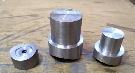
The first photo shows the blanks for the three components. In each case, I cut the base with a fly cutter so it would sit on the smokebox or boiler, and turned a flat so that the blank could be held on an arbour for machining. This is most clear on the left hand part, which is the base of the chimney and I turned it upside down for the photo.
The first photo shows the blanks for the three components. In each case, I cut the base with a fly cutter so it would sit on the smokebox or boiler, and turned a flat so that the blank could be held on an arbour for machining. This is most clear on the left hand part, which is the base of the chimney and I turned it upside down for the photo.
Now it is on the mill. This is the fixture that holds it and allows it to be rotated (by hand). The spring is supposed to hold it up against the stop, but I found I had to substitute a stronger spring and still had to assist with a thumb pressed against the top of the dome. Just don't tell H&S.
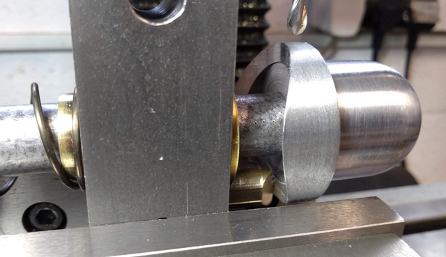
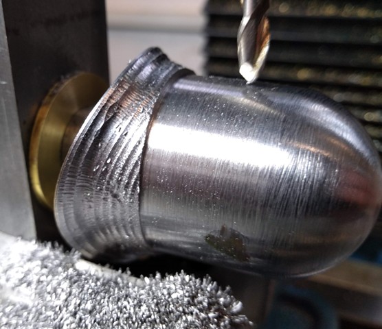
Now I can attack the base with a ball nose cutter to get most of the metal off. Yes, it is pretty rough, but that is because it is impossible to hold the workpiece rigidly as it is rotated.
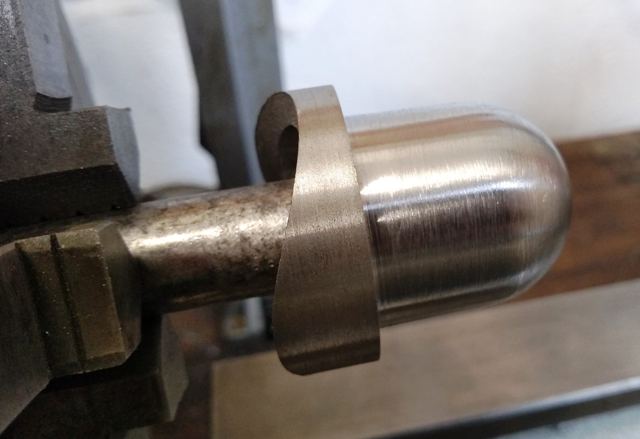
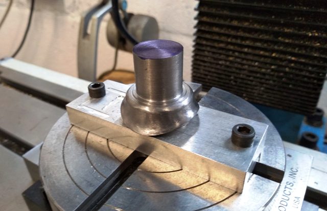
The next few photos show the machining of the dome as an example. This picture shows it mounted on the arbour and held in the lathe. I have turned the taper (the Adams dome is quite a subtle shape. It is not parallel sided but tapers at a slight but noticeable angle. I have seen a few models that get that wrong). The top of the dome was turned using a radius tool - a very useful device.
This is the tedious bit. Once I had removed as much material as I dared, the rest of it has to be done by filing. It was removed from the mill, still on the arbour, clamped in the vice, and away we go. Keep watching the profile from different directions, and look at the shape from different angles and different lighting. File away and gradually all the humps and bumps will disappear.
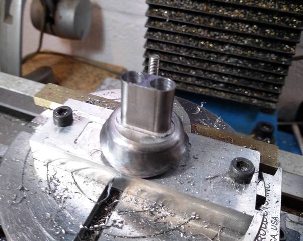
This is the safety valve cover. I decided to do it all in one piece. Here the base has been finished just as for the dome, and it is on the rotary table in a fixture that allows it to be moved along the X-axis of the mill so that it can be rotated about the centreline of each valve in turn. I measured the sliding diatance with a dial gauge to get it correct.
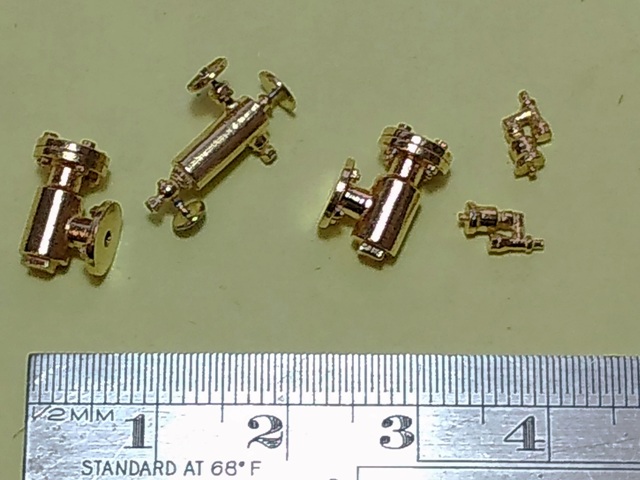
The other boiler fittings were made by 3D printing in brass. My input was to create the solid model files for each of them, working from drawings and photographs, and hand over the necessary cash. Here are the clack valves, the lubricator mounted on the side of the smokebox (actually there are two, one seems to have escaped the photograph), and the cylinder lubricators that were actually mounted on the footplate next to the smokebox. I think they all turned out pretty well. The handwheels and stems of the lubricator were too fine to be printed, so I turned them separately and soldered them in place.
Still to be done are the whistles and the steam take-off on the firebox.
Still to be done are the whistles and the steam take-off on the firebox.
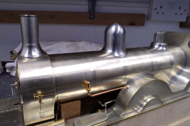
At last it's starting to look like a locomotive.
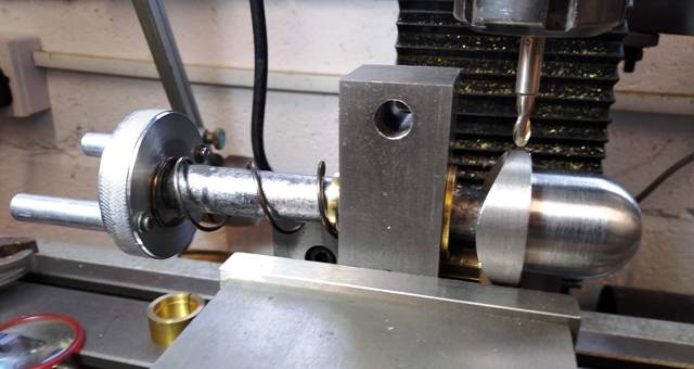
How does it work? Notice the brass peg near the bottom of the picture that the curved base of the dome is up against. As the dome is rotated, it moves axially in and out according to the shape of the base. And so the cutter path follows the base profile. Clever, huh?
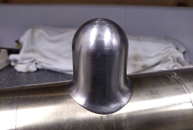
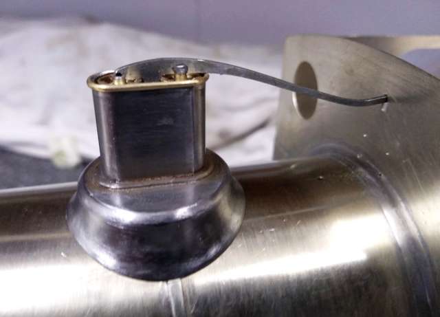
The safety valve cover was finished with a piece of half-round brass wire soldered around the top edge. The valves and lever drop into place.
