Nick Baines • Model Engineering
Drag Beam Assembly
And I thought the drag beam would be just a plate across the rear of the frames with a slot for the drawbar. Actually it was a lot more complicated than that. On studying the drawings and photos, I realised that the cab steps, injectors and all the injector pipework were hung off the beam. So it ended up with various brackets and lugs to attach things to.
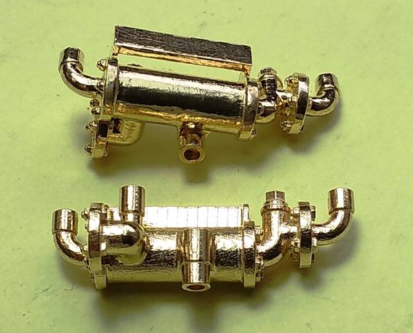
I had Shapeways 3D print the injectors in brass from my solid model. That was a lot easier than machining, and the photo below shows them as received. The layering looks a lot worse in the photo than in reality (to my eye, at least). It depends very much on how the light catches them. A little polish on the visible surfaces brought them up really well.
I thought the cost at about £30 the pair was reasonable and competitive with casting for such a small number. Dimensionally they are dead accurate, and there was no messing about with drilling out holes for the pipework. And they had to be brass because the prototype injectors were unpainted, and nothing looks like brass so much as, well, brass.
I will be back to Shapeways for more fittings. Unlike plastics, I don't think we will be 3D printing metals at home any time soon. Apart from the cost of the machine, it requires a high power laser, high temperatures, coolant supply and goodness knows what else. Not something to run in the spare bedroom.
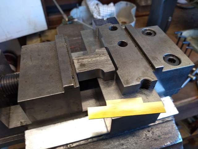
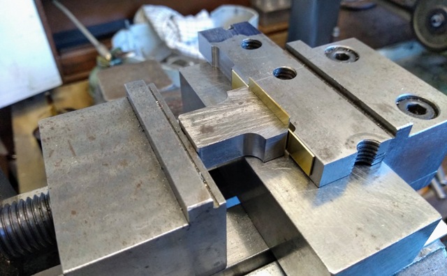
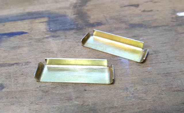
The steps have a considerable turn-up at the sides, and counting the loco and tender together I shall need a dozen of them, but only in two sizes, so I made up a press tool using two pieces of steel from the scrap box. Here it is, together with a brass blank ready for pressing.
The blank is loaded into the press and aligned by eye, which proved quite good enough.
And pressed.
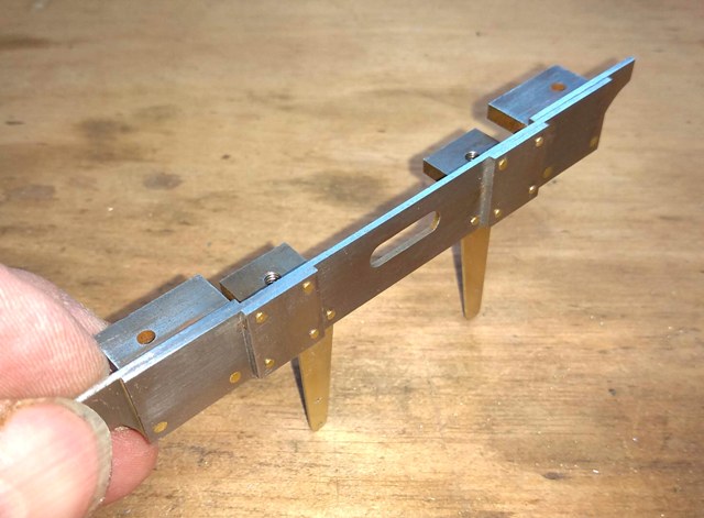
In retrospect, I made it more complicated than necessary, WIth more thought, and more machining, the parts count could have come down considerably. I broke my rule of making things from as few parts as realistically possible, because the attachments take time and is where misalignments occur.
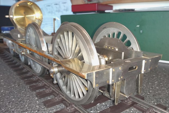
Here it is temporarily in place and supporting the footplates, just to make sure it all goes together.
Here it is temporarily in place and supporting the footplates, just to make sure it all goes together.
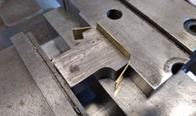
And pressed.
Then the upstanding tab was folded over by pressing on it with another piece of bar and tapping it down to form the angle at the back of the tread.
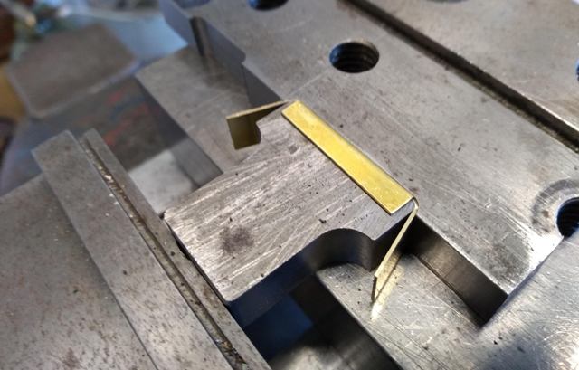
Released from the press and trimmed to size.
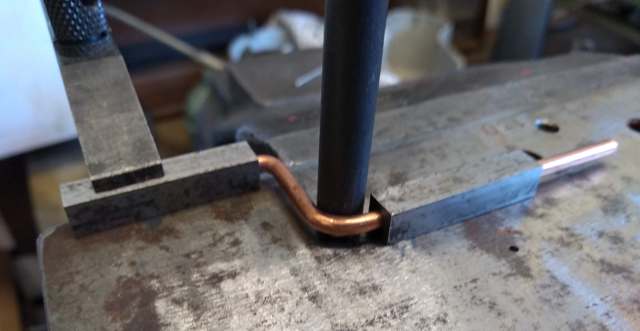
The injector pipework was simulated using straightened copper wire except for the feedwater pipe from the tender which was a lot larger and required 3 mm diameter copper rod. It has two right angle bends (of different radii, of course). Time for a bending jig.
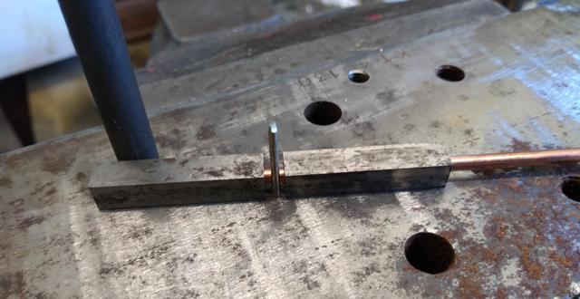
I took two pieces of ¼ in square steel and drilled and reamed them 3 mm through. They are used to hold the copper rod (without marking it, as any form of gripping tool would) and keep it straight between the bends. The first, tighter bend is formed about a 1.5 mm diameter pin. The large upright rod stops one end moving when the other end is bent.
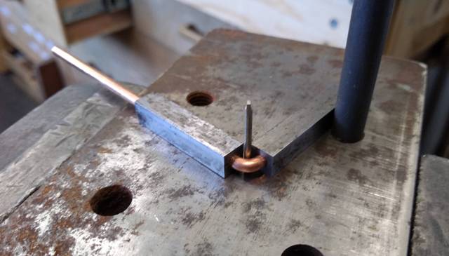
The second bend is formed about the larger rod. One end of the copper, in its holder, is clamped in place and the other end is bent around that rod. The difficulty is getting the spacing between the two bends correct. I measured it from the job as best I could but there is always a bit of spring, even in copper, so I was prepared for some trial and error. As it turned out, it was close enough first time.
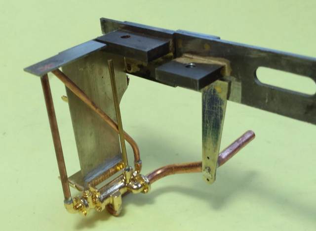
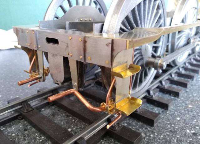
Here is the drag beam assembly, and finally in place. I like the visual effect of the tangle of pipes.


