Nick Baines • Model Engineering
Frames, horns and axleboxes
To make the frames, I cut and riveted together two blanks of 1.6 mm steel. If that sounds thin, my defence is that it is close to scale thickness. My aim is to compromise visible dimensions no more than I have to. I don't think that strength is in question here, particularly because the loco is not intended to haul passengers, but rigidity might be. It is braced where the prototype was braced, and so far it all seems stiff enough. If it is not, I expect that the boiler and superstructure will add considerably more stiffness.
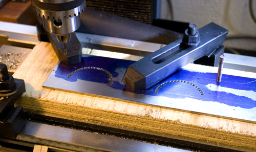
The frame profile involves some very large radius curves on the top edge which would be difficult to mark out accurately. I did it on two steps. Using the CAD model, I first compiled a table of coordinates of holes to be drilled for the various rivets and bolts. I clamped the frame blanks to a backing piece which is itself clamped on the mill table, drilled a couple of strategic holes and made up some pins to go through the frames and into holes in the backing piece, so that the frames could be removed and replaced in exactly the same place. Using the mill DRO, I could locate and drill the holes accurately. While at it, I drilled sets of holes around the openings for the cylinders and horns, which could subsequently be sawn away.
The frame profile involves some very large radius curves on the top edge which would be difficult to mark out accurately. I did it on two steps. Using the CAD model, I first compiled a table of coordinates of holes to be drilled for the various rivets and bolts. I clamped the frame blanks to a backing piece which is itself clamped on the mill table, drilled a couple of strategic holes and made up some pins to go through the frames and into holes in the backing piece, so that the frames could be removed and replaced in exactly the same place. Using the mill DRO, I could locate and drill the holes accurately. While at it, I drilled sets of holes around the openings for the cylinders and horns, which could subsequently be sawn away.
Back at the computer, I printed a full-size template of the frame, carefully located it and used it to mark out the frame outline by going round it with a scriber.

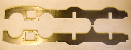
The frames were then cut out using a combination of drilling, sawing, filing and cussing. Actually it wasn't at all bad. One of the benefits of using relatively thin material is that it can be removed quite quickly. A few dimensions had to be accurate, mainly the cut-outs for cylinders and horns previously mentioned, so when the bulk of metal had been removed, the frames went back on the mill to finish those parts exactly to size. The bogie frames were made in the same way, but the rest of the parts are rectangular or nearly so and were straight forward to mark out, saw, and then finish on the mill.

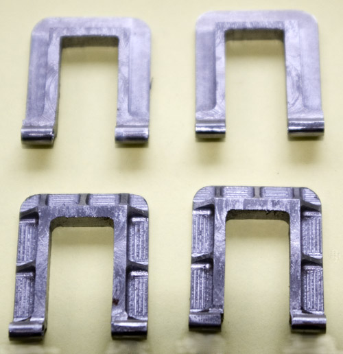
The hornguides were machined from solid. Now this did get undeniably tedious. The cuts were easy to work out from the CAD model, but there was a lot of machining using a small diameter cutter. The rear axle is completely hidden under the cab, so I omitted the ribs on two hornguides to save time. I expect it would be a lot quicker using CNC, but I'm getting into this one step at a time. Having a DRO is a massive step forward on a manual mill, and having fitted it, I wouldn't be without it. I also thought about 3D printing a master for casting, but wondered whether it was really worth the effort for just one loco.


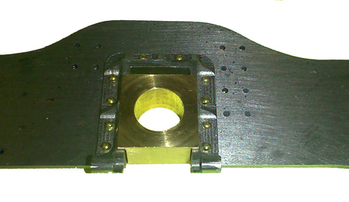
Hornguide rivetted to the frame. The axlebox is a straight forward turning and milling job.


