Nick Baines • Model Engineering
Bodywork
The difficult bit of the bodywork is the part where the driving wheel splashers, boiler, firebox and cab front all merge into one another in best Victorian engineering fashion. Lots of curves, and reverse curves, going in different directions and intersecting with one another. It must have been as big a nuisance on the prototype as it was on the model, but in those days labour was cheap and nobody was counting the hours. Without question, these features make the locomotive so attractive and give it much of its character.
First up was the smokebox, which is just a skin wrapped around and soldered to formers. The angles of the section of the footplate in front of the smokebox are rivetted to the frames in a rather prominent way. The South Western mostly used countersunk rivets, which makes it easier for the modeller, but this is an exception. I simulated the rivets with entomological pins that were originally purchased for an O gauge project, but they turned out to be too large. They were just the right size for Gauge 3.
First up was the smokebox, which is just a skin wrapped around and soldered to formers. The angles of the section of the footplate in front of the smokebox are rivetted to the frames in a rather prominent way. The South Western mostly used countersunk rivets, which makes it easier for the modeller, but this is an exception. I simulated the rivets with entomological pins that were originally purchased for an O gauge project, but they turned out to be too large. They were just the right size for Gauge 3.
For the skin, the outside curve was easy to roll using rolling bars, but the reverse curves needed a lot more persuasion. Once the front and rear plates were soldered up, the spacers between them were removed, the lower ends of the sides were soldered and the ashpan was added (only the sides and front of the ashpan, it has to go on over the motor).
A quick check to make sure everything fits in place.
The boiler is just a rolled cylinder. The firebox is fitted over formers like the smokebox, but it is a lot longer and took more effort. Here is the skeleton, compristing front and rear plates and spacers.
Now the fun starts. The tops of the splashers start in front of the leading driver, wrap over both wheels with a connecting piece between them, and then climb up to finish where they meet the cab front. I did think about making them integral with the cab front, but that was getting way too complicated. It means I'm going to have a joint line on the front of the cab to disguise, but I decided that was better than making everything in one piece, while curving it this way and that and still preserving all the dimensions and alignments. I have a photo of a T3 under construction at Nine Elms, and I see that the South Western came to the same decision.
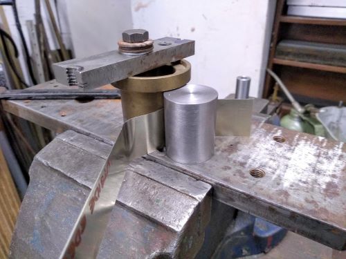
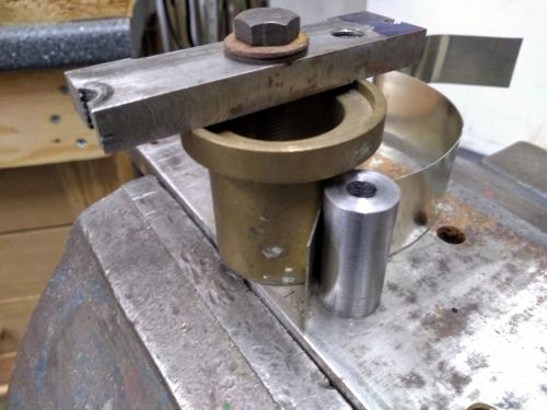
Here is a splasher top being bent to shape. My bending jig is a cylinder of the correct diameter (slightly smaller than the bend radius to allow for the spring in the metal), with another cylinder, obviously out of the scrapbox, as a clamp. I found it best to start in the centre and work outwards. The strip of metal is longer than required and cut to length when finally shaped. It is a matter of going slowly and carefully, checking frequently with the drawing and marking the workpiece where each bend occurs.
Here is a splasher top being bent to shape. My bending jig is a cylinder of the correct diameter (slightly smaller than the bend radius to allow for the spring in the metal), with another cylinder, obviously out of the scrapbox, as a clamp. I found it best to start in the centre and work outwards. The strip of metal is longer than required and cut to length when finally shaped. It is a matter of going slowly and carefully, checking frequently with the drawing and marking the workpiece where each bend occurs.
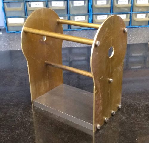
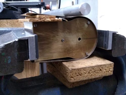
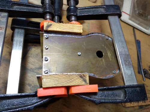
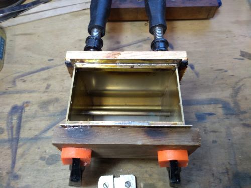
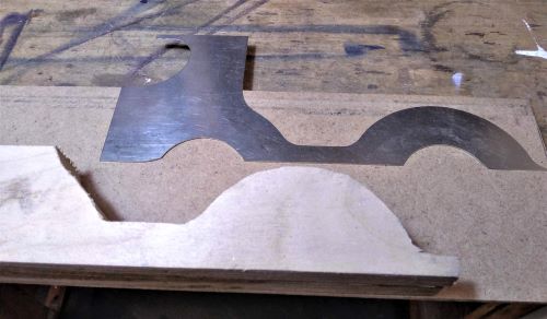
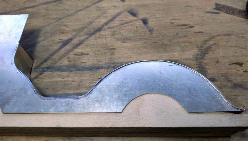
To assemble the splashers, I cut a piece of wood roughly to size and shape (undersize) to support the side that is in the photo. Then the splasher top is pushed up against the side and soldered in position.
The second photo shows that the top is slightly proud of the side. That is intentional. It is cut oversize and, after soldering, the excess is filed away to leave a nice sharp corner.
Next I had to attach the splasher assemblies to the boiler and firebox, and this is where we get into dealing with intersecting curves in three dimensions.
Initially clever me thought that, because I had made a 3D model of the loco on the computer, I could develop the splasher top on a plane surface, cut the metal to the drawing, bend it up and it would fit. Oh yes, that will work (as long as everything else is to the drawing). Which, unfortunately and predictably, it wasn't. When making assemblies of sheet metal parts that have to be bent to shape, they won't come out exactly to drawing unless you make some very good bending jigs. That might make sense for multiples but not for a one-off model. My attempts were close enough to drawing for visual effect, but still left were unacceptable gaps when I tried to fit the splashers to the firebox.
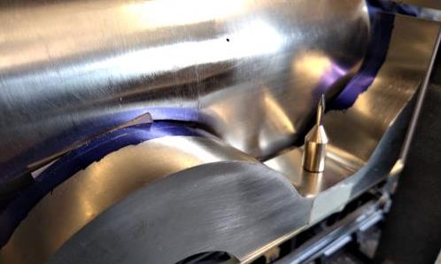
So it was back to the traditional method. To start off the splasher top was cut to be a constant width. Once soldered to the splasher sides, the assembly was offered up to the boiler-firebox assembly, and the outline of the boiler and firebox was marked on the splasher top. The funny little gizmo placed on top of the splasher is a tiny scriber that I can hold up against the side of the firebox as I run it along the splasher top so that the point maintains a constant distance from the surface of the firebox and gives me a line to saw to.
Then the splasher top was sawn and filed to fit. Much easier said than done. Actually it was an awful lot of cut-and-try, removing little bits of metal here and there, but eventually it fitted nicely in place. Much patience was necessary. Sorry, I didn't say it was easy, did I?
When I'd finally got both splasher assemblies to my satisfaction, they could be attached to the firebox. First of all, I used an assortment of squares, clamps, packing and stickly tape to make sure everything was straight and square.
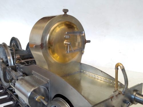
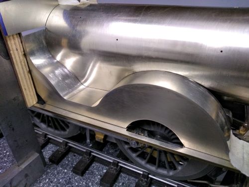
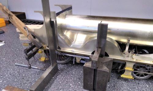
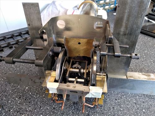
Then I added a few solder tacks to hold everything in position, and moved the whole body to a cradle for further assembly. The cradle is very useful and well worth the short time it took to make out of scraps of plywood, because I can now move the body around without the weight of the chassis, and it also saves getting flux and filings on the chassis which do it no good at all.
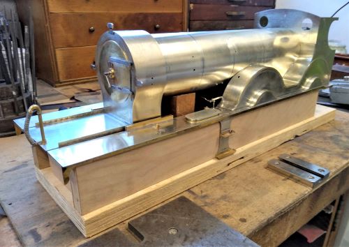
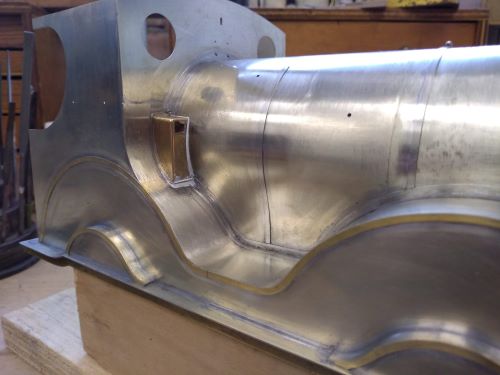
Now we have a small diversion. On the right hand side of the body there is a small casing where the reversing lever enters the cab. It is a bit fiddly because it sits on the splasher of the rear driver and the side is up against the firebox - two curved surfaces to match up with. I prefer making things like this from solid rather than building them up from pieces of sheet. Generally the rule is the fewer parts, the better. The casing was cut on the end of a piece of brass bar. The photo shows the firebox curve being cut on the mill using the rotary table.
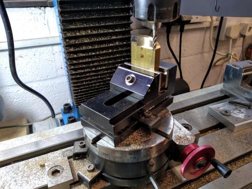
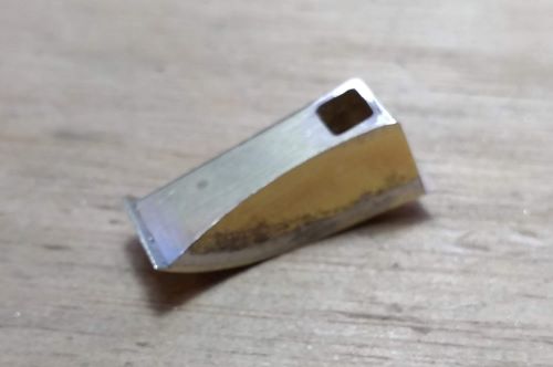
Once parted off and soldered to a flange, it looks like this.
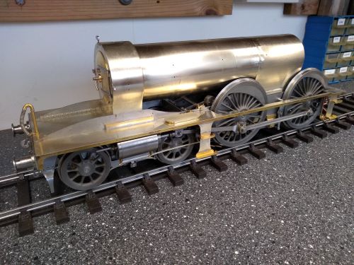
And here is the body, with all the seams soldered up and that reverser casing in place. Yes, there are gaps. I didn't get it quite right but it wasn't worth making another one, because I can fill the gaps later and under a coat of paint no-one will know. I have also added the brass beading around the sides of the wheel splashers and the little splashers over the coupling rods. More fiddly marking out and cutting - when will it end?
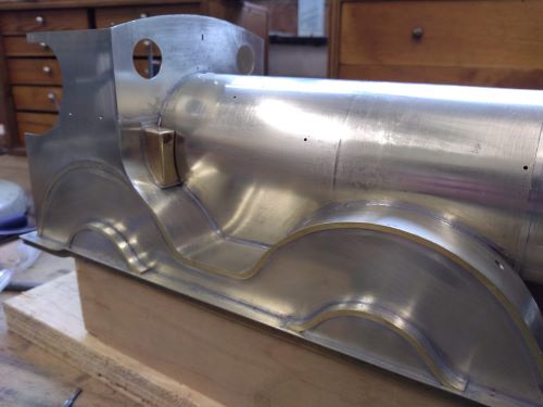
Not yet is the answer. The joins between the splashers and cab front, and the boiler and firebox, are reinforced with angle iron, bent and twisted to follow the contours. That must have kept the Nine Elms blacksmiths busy. I was not going to make them from commercial brass angle, which would require far too much time making special bending tools. I decided to make the horizontal and vertical parts of each angle separately, solder them in place and rely on solder to fill any gaps between them.
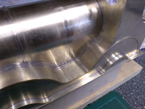
The next photo takes us back in the timeline some distance. Before soldering the splasher assemblies to the firebox and boiler, I wrapped a sheet of tracing paper around the boiler and traced the line of the splashers. That was my template for marking out and cutting the vertical parts of the angles. Of course there was some more filing and trying until they fitted well enough to be soldered in place. I did the horizontal parts in similar fashion, using templates traced on the splashers.
The next photo takes us back in the timeline some distance. Before soldering the splasher assemblies to the firebox and boiler, I wrapped a sheet of tracing paper around the boiler and traced the line of the splashers. That was my template for marking out and cutting the vertical parts of the angles. Of course there was some more filing and trying until they fitted well enough to be soldered in place. I did the horizontal parts in similar fashion, using templates traced on the splashers.
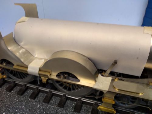
All of the parts for the angles were marked out, sawn, filed, fitted, soldered and cleaned up. Here is a photo of the right hand side to compare with the one above - "before" and "after" if you like. You can see how awkward the angles are. Before this photo I also filled in the gaps around the reverser casing and added the last remaining lagging bands.
And here is the left hand side.
