Boiler
Before embarking on the boiler, there was a decision to be made, one that arises frequently in these old locos with large driving wheels and low-set boilers. The boiler diameter was often the largest that could be fitted between the wheels, and the problem with modelling is that the back-to-back dimension of O finescale is smaller than that of the prototype, and smaller than the boiler diameter. Solid modelling shows up the conflict very well.
Nick Baines • Model Engineering
The wheels are drawn to finescale dimensions, and the boiler assembly to prototype dimensions, and the clash is obvious. If you look closely you can also see another clash between the boiler and the crank. Laurie Griffin's cranks are actually slightly longer than scale. Solid modelling is a great tool for revealling problems like this.
So what to do? One solution is to cut away the boiler to provide clearance for the wheels.
So what to do? One solution is to cut away the boiler to provide clearance for the wheels.
Then the cutaways for the driving wheels must be hidden by the splasher and the splasher must blend into the boiler whereas on the prototype is stands separate.
There is, of course, no right answer. On previous models I have used both solutions. You have to make an individual judgement. In this case I decided, based on the prototype photograph, that the large boiler was a very striking feature that gave the loco must of its individuality, and if I made it smaller the loco would lose a lot of its unique character.
Yes, I can hear the ScaleSeven modellers sniggering. First, mine are commission models so the clients get the scale that they ask for. Second, if I were doing it for me I would still make it finescale so that I can run indiscriminately on many people's layouts. I don't have and don't intend to have a layout of my own. And third, the prototype clearance between the boiler and wheels is very tight. If your Scale- Seven wheels have any sideplay at all (they will), and if they are not absolutely dead square on the axles (they won't be), they will rub and you will still have to compromise somewhere. Okay, now I will climb off my soapbox and get on with the construction.
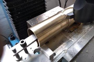
Because of the machining that would be involved in cutting clearances for the driving wheels, I decided to make the boiler from thick-wall tubing that was almost the right outer diameter. Here I am turning the boiler portion to diameter in the lathe using a fixed steady. The boiler is smaller in diameter than the combustion chamber and the firebox.


The other option is to reduce the diameter of the boiler assembly below scale so that it fits between the wheels. The firebox and smokebox diameters also have to come down to match.


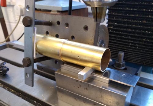
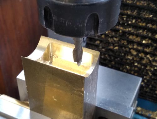
The firebox extention was also machined from brass. What will be the upper surface was fly cut to match the diameter. It was then hollowed out, and parted off using a slitting saw.

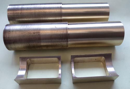
And here are the pieces of the boiler-combustion chamber-firebox assembly.
There are shaped rings between the boiler and combustion chamber, and the boiler and the smokebox. These started life as pieces of plate, drilled out in the centre, mounted on an arbor (I used one of my driving wheel arbors that was the right diameter), and the outer shape was made with a form tool.
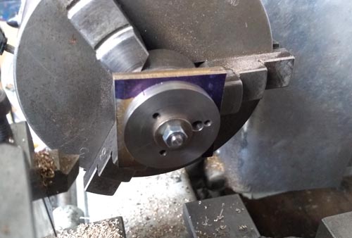

Here is a composite photo showing the split collet that I made to hold each piece in the chuck separately, a turned disk, and the ring that is left when the centre of the disk is drilled and bored out.
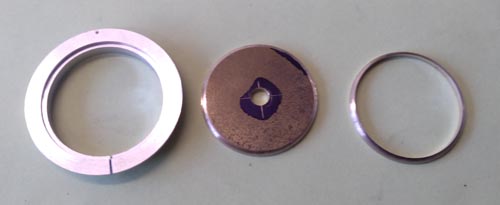
Everything was then soldered together. I had to use my little gas torch to heat this mass of metal sufficiently even to soft solder it.

Now the fun starts - cutting the clearances for the driving wheels. First I made a mounting plate to hold the boiler assembly horizontally on the mill.

The clearances were cut with a flycutter. Using the DRO, I set the zero on a convenient corner of the boiler assembly then moved to the centre of the driving wheel splasher, using X and Y dimensions from the CAD model. Modern technology makes this sort of thing so much easier than it once was. Incidentally, the splasher centre is not coincident with the driving wheel centre, it is set slightly higher to allow for vertical motion of the axlebox.
First cut one side, then flip the mounting plate around to do the other side.
First cut one side, then flip the mounting plate around to do the other side.

A trial assembly of the boiler, footplate and chassis to make sure the driving wheel cutouts were in the right place. Whew.

Then it went back on the mill to drill holes for all the boiler fittings. I clamped the boiler to an adjustable angle plate to set it at different angles to get all the holes in the correct places and perpendicular to the boiler. Once again, the combination of CAD and DRO made this easy.
