Chassis details
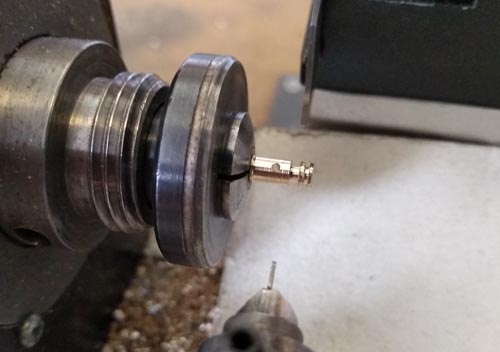
This is a fairly plain prototype, compared with some, but there are a few details to add below the footplate. First up is the cylinder drain valves. From the scanty information, the valve bodies appear to be spherical - tricky to make, but what else on a loco is that shape? Handrail knobs, of course. So the basis was a commercial handrail knob. First, it went in the lathe. The shank was too small for the chuck, and watchmakers' collets that small are horrendously expensive, so I made a split collet to hold it. It is just a bush of the correct inner diameter, a mark against the no. 1 jaw to make sure it goes back in the chuck the same way every time, and a saw cut to allow it to clamp. Then the end of the knob was drilled for the drain pipe.
Nick Baines • Model Engineering
The drain pipes are cranked little pieces of wire were soldered in place, The operating rod goes through the guard irons so I left it over-long until they were added.
The valve and injector bodies are made the same way - turnings with a cross hole for the feed pipe. I have a jig for drilling cross holes through cylindrical components.
The pipework required a couple of bending jigs, which are just scraps of metal with pins of the right size and spacing, around which nickel silver wire can be bent, Toolmakers clamps are used to hold the wire or simply act as stops.
It's difficult to be specific about the diameter of the pins, because it depends on the material being bent, its hardness, and the bend radius. For the nickel silver wire usually available, I aim for a cylinder diameter of about 80-90% of the finished bend to allow for the spring in the wire. Soft copper has next to no spring so 100% is appropriate. I don't get too obsessed about it, it is more important that everything lines up and looks right than getting the bend radii exact.
The LH picture below shows the initial setup for a 180° bend, and the RH picture shows the bend made and how the notch in the jig is used to cut the ends of the wire to the correct size once it is bent.
Here is another bending jig used for an S-bend of two different radii. And when the pipe bends in two directions not in the same plane, it needs more blocks and clamps to hold everything in place. Work it out in advance and do one bend at a time.
The feedwater injectors are mostly hidden behind the side screens, but the bottom projects below the footplate, along with the clack valve and pipework.
Four knobs were soldered in place below the cylinders. The cross holes were used to connect up the operating cranks.
The jig is in two parts held together with cap head screws. The upper has a vee-notch to hold the material being drilled, and above that is a hole dead in line with the tip of the vee, in which goes a guide for the drill. There is a separate guide for each drill size. For very small drills, the guide is bored out with a larger clearance size, and only the last millimetre or so is at the actual size required. That saves drilling the guide with a very deep hole and a small drill, which is always tricky.
Here is the valve body being turned and parted off in the lathe.


Lastly, I needed a bracket and clamp to secure the free end of the feedwater pipe to the chassis. On the prototype it is connected from here to the tender pipe with a flexible hose. Very few people try to model that in O gauge. I suppose I should, but no-one has commented so far. Let's see how much longer I can get away with it. Anyway, back to the clamp. It is a U-shape with lugs and it is made in a press tool that has a U-shaped groove in one side (cut with a ball nose milling cutter). The material is pressed into the groove by a hard steel wire of the correct diameter.


Once pressed, the material is cut to size and the bolt heads are simulated using the riveting tool. They are too small to reproduce accurately.


