Driving Wheel Splasher
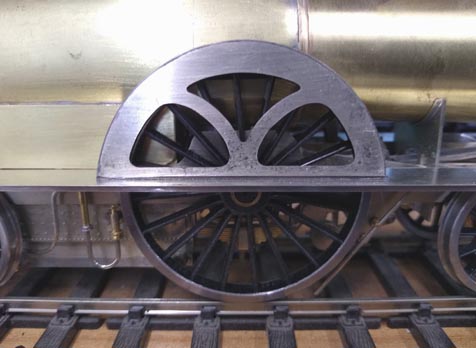
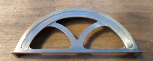
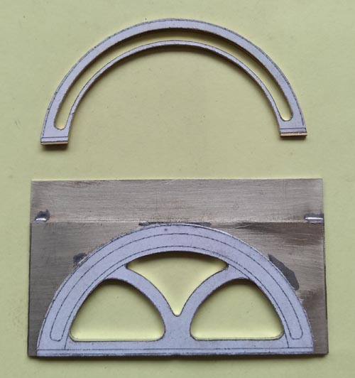
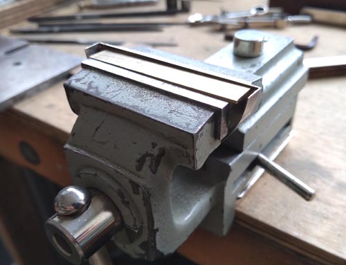
Like many locos of that era, the driving wheel splasher was decorated. Not as much as some, but enough. It is a component that really catches the eye, so a neat job is essential to the appearance of the model. The splasher front has three cutouts and the polished brass surround also has a cutout. For both parts I soldered sufficient blanks together to do them all in one, and printed parts of the drawing on to self-adhesive paper to give the outlines.
Nick Baines • Model Engineering
Everyone asks how I cut it out. The secret is, there is no secret. Drill a few strategic holes to get the saw blade through, cut out with the piercing saw close to the outlines, and finish with files. Don't rush it and keep checking.
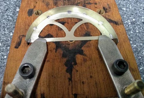
The splasher top was then soldered to the front. The top was cut to width but slightly too long and rolled in the rolling bars. The photo shows it tacked into place, and when I was happy with the fit, it was seamed all the way round.
The splasher top was then soldered to the front. The top was cut to width but slightly too long and rolled in the rolling bars. The photo shows it tacked into place, and when I was happy with the fit, it was seamed all the way round.
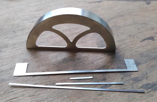
On the prototype the splasher is attached to the footplate with angles. If it was just the front it would be easy to do with an angle section, but the sides where they meet the footplate are not vertical and the angle is not 90°. So I simulated the angles by means of a base, initially cut oversize, and the uprights by separate strips.
The excess at each end was removed with a saw and filed back level to ensure that the splasher would sit nice and square.
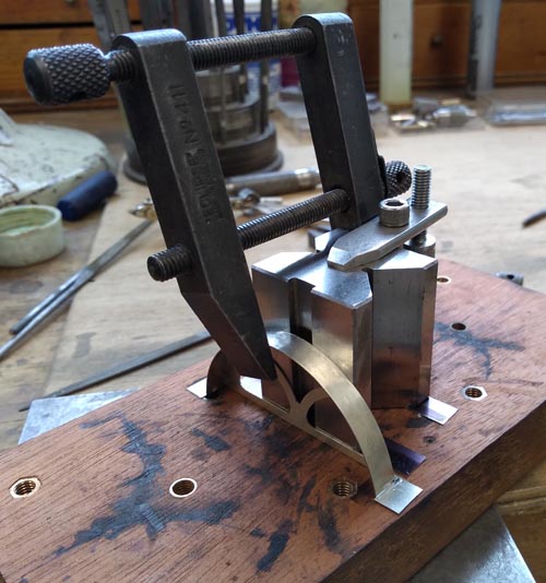
All clamped up for soldering the base piece.
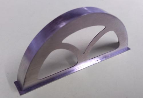
And here it is with the base attached and cut back to size. Following this, the upright pieces were added.
And finally the brass surround was soldered in place. When the model is finished the brass will be polished.
Checking that it fits.
