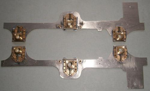
The hornguides were soldered to the frames. The accurate cutouts in the frames ensures that the axle spacing is correct. The photo also shows the springs and keepers in place.
Frames and spacers
I drew the frames in CAD and printed it full size for O gauge. I then cut two blanks of 0.7mm nickel silver, stuck them together with double-sided tape, and stuck the drawing in place using more tape. I use this method for anything with a complicated shape.
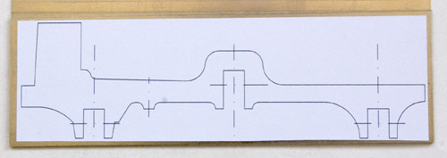
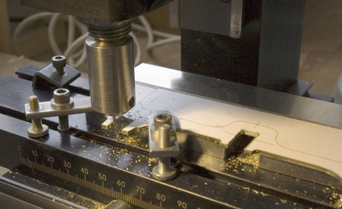
Most of the frame was cut out using a fretsaw. People seem to think this is a laborious process, but with a new blade I find it goes quite quickly. And with a bit of practice, I can cut very close to the outline, leaving only a little filing to do. The cutouts for the axle bearings are critical because in this case they act as hornguides. I milled them to ensure that the sides of the slots are truly parallel and the correct width.
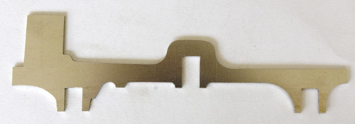
The upward extensions on the frames support the front and back plates of the smokebox. The wrapper over the smokebox and cylinders means that the smokebox cannot be separated from the frames, so I made them integral.
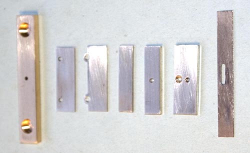
The spacers are 0.7mm nickel silver where they are visible, and 1.6mm elsewhere. They were all machined to width to ensure that the frame spacing is correct. The photo also shows the front beam with blind holes for the buffers, and the drag beam.
The axleboxes and hornblocks are Meteor Models products. I used them for the fine detail on the hornblock casting, which is visible on the finished loco. A lot of surplus metal has to be cut away, and some filing of the guides is necessary to make the axleboxes a nice smooth fit.
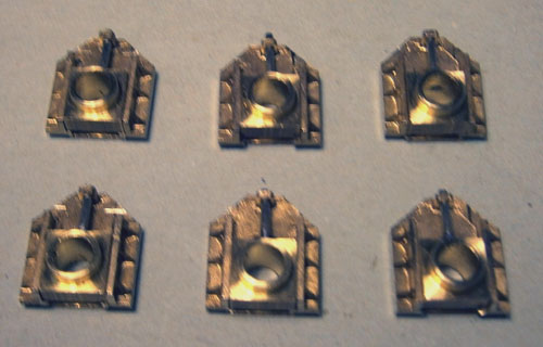
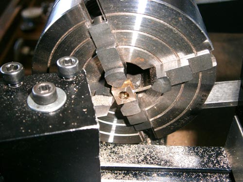
The axleboxes for the driving axle had to be cut back to make room for the eccentrics. Unfortunately I forgot to do this before fitting the spring guides, so it was a bit tricky to hold them in the 4-jaw chuck.
Nick Baines • Model Engineering


