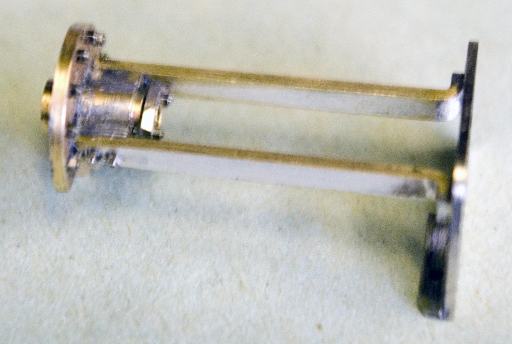
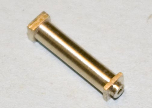
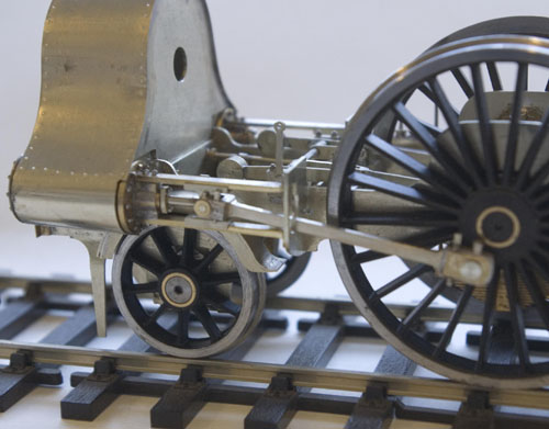
Slidebars are easy to make, the problem is assembling them. They are attached to the cylinder cover at one end, and the motion plate at the other, and of course they must be dead parallel. At (a) is a jig I made up to clamp them at the correct spacing, with a shaft to hold the cylinder cover in place (b). The cylinder cover (c) is a turning with the slidebar mounts soldered to what would be the piston rod gland. The photo also shows off the Scale Hardware bolts nicely. I solder these in from the rear, with just enough solder to penetrate and form a little ring around the nut that gives the appearance of a washer. The slidebars were soldered in place, then the assembly was pushed into the cylinder, the motion plate was temporarily screwed to the frame, and the slidebars were soldered to it. The whole thing is then a separate assembly that can be removed for painting or maintenance without disturbing any critical alignments.
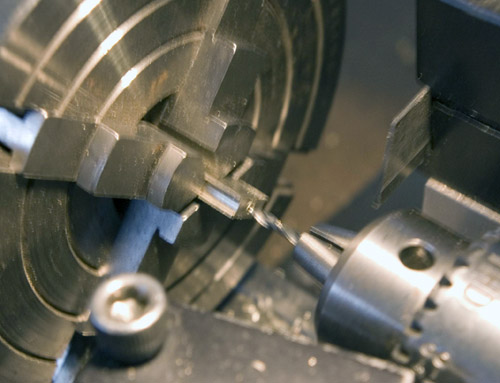
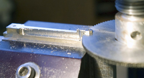
The crossheads are made from solid. First a strip of nickel silver, long enough for two crossheads, was machined to width. Channels for the slidebars were cut and checked that they would slide easily. The strip was then mounted in the 4-jaw chuck in order to drill the ends centrally for the piston rods.
The crossheads are made from solid. First a strip of nickel silver, long enough for two crossheads, was machined to width. Channels for the slidebars were cut and checked that they would slide easily. The strip was then mounted in the 4-jaw chuck in order to drill the ends centrally for the piston rods.
(a)
(b)
(c)
(d)
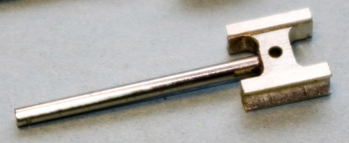
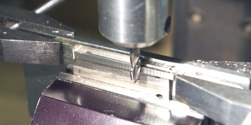
Then it was attacked with a milling cutter to remove unwanted metal on the profile, and the web was thinned down where the conn rod will go. Piston rods were inserted and soldered in place. That blocked off the holes for the conn rod pins, so they were re-drilled.
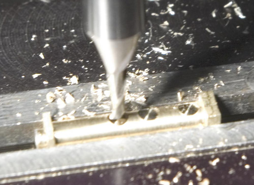
On the RHS of the Webb rebuilds is a vacuum pump mounted on the motion plate and driven from the crosshead. The pump body was turned from square bar to leave the flanges in place, and locations for the pipe connections and safety valve were spotted in place using an endmill.
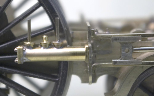
Here is the pump assembled and in place. The pipes were later made to disappear under the footplate. More of those Scale Hardware bolts on the flange.
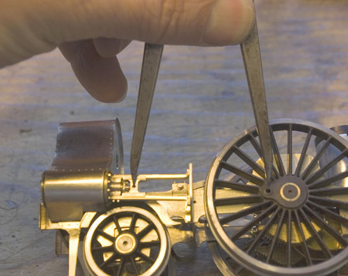
The conn rods are an awkward shape, with a large rectangular boss at the big end, and a large fork at the little end for the crosshead. Both ends on the prototype have split bearings with cotters and pins. I considered building it up, but really the only way was to make it from solid. It was machined from a piece of 10 x 6 mm nickel silver, which is large enough to leave some material for clamping purposes.
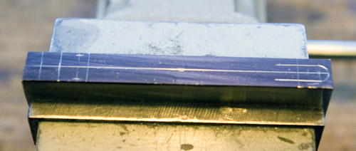
The key dimension is the distance between centres, which I took directly from the model and transferred to the material. I marked out a few more important dimensions, although that is not strictly necessary because everything is located from the x- and y-axis scales on the milling table. But it is good to have a visual check to make sure I have not miscounted the number of turns (this was before I fitted the mill with DROs).
The key dimension is the distance between centres, which I took directly from the model and transferred to the material. I marked out a few more important dimensions, although that is not strictly necessary because everything is located from the x- and y-axis scales on the milling table. But it is good to have a visual check to make sure I have not miscounted the number of turns (this was before I fitted the mill with DROs).
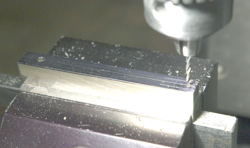
First the holes were drilled - if they are wrong, anything done subsequently is a waste of time. Then the outer shape was milled. Most of the cuts are parallel to the x- or y-axis, but the centre part of the rod tapers. The milling vice was mounted on the rotary table, so that I could increment the table one way then the other to get the correct taper.
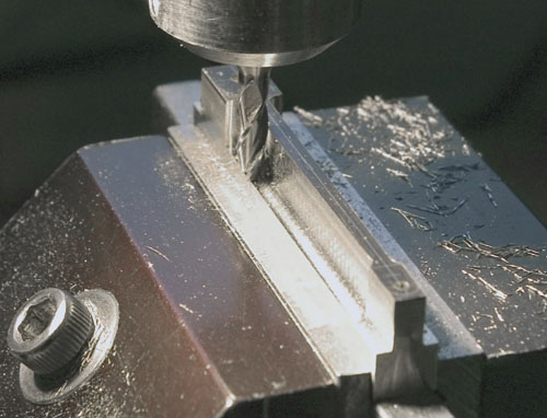
The rod was parted from the rest of the material, turned through 90°, and clamped to a plate held vertically in the vice so that it could be machined to width. The rod is quite thin between the two ends. After doing one side, I turned it over and put some packing between the rod and the plate to prevent the rod from bowing under the pressure of the cutter.
Finally cleaned up to remove the machining marks and decorated with bearings, cotters, pins and oil pots. It's a lot of work, but the rods are a very visible part of the locomotive.
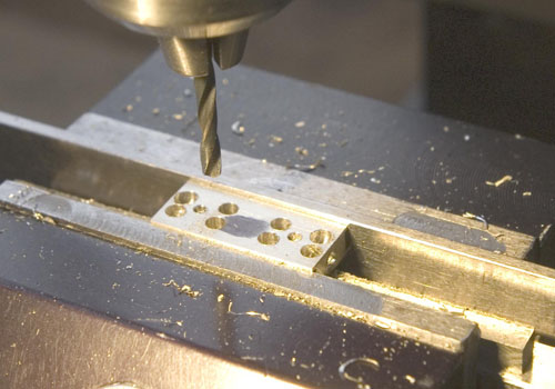
On to the mill, holes for the conn rod pin were drilled, and other holes were drilled where metal was to be removed to get the final shape.
Finally, the crossheads were separated and polished up to remove the machining marks.
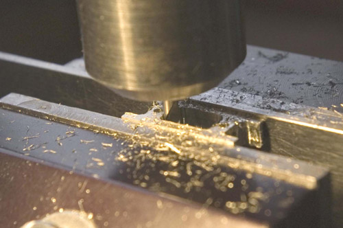
The forked end was cut using a slitting saw.
Slidebars, crossheads and conn rods

Nick Baines • Model Engineering


