Footplate
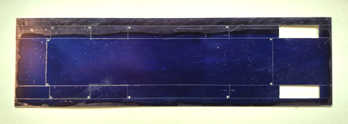
The footplate was marked out in 0.25mm nickel silver. This is actually thicker than scale, so I filed the edges, where they were visible, at an angle to reduce the apparent thickness. Here I have marked out and started cutting (with a oiercing saw) the cutouts for the chassis and wheels. It is not strictly necessary to drill holes at the corners because with care a fine saw blade can be persuaded to go round a corner, but it helps.
Nick Baines • Model Engineering
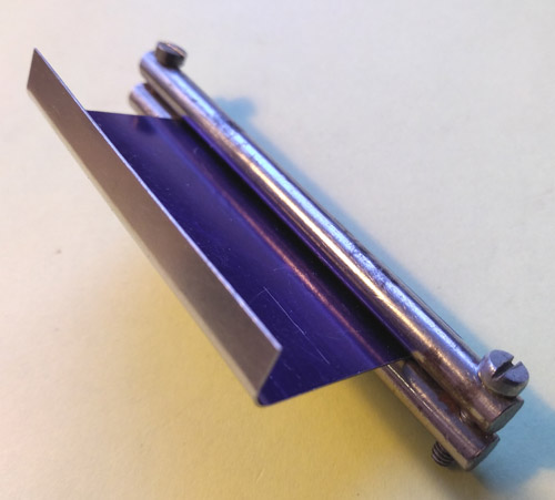
The front part of the footplate is turned down to meet the buffer beam. This was a separate part. The bend radius is too small for my rolling bars, and for times like this I have pairs of bending bars that screw together, trapping the material between them. I have several pairs of different radii, and I chose the most suitable radius, clamped the material and bent it by hand. In the photo it is considerably oversize, and was subsequently cut to fit.
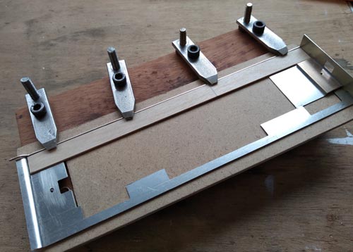
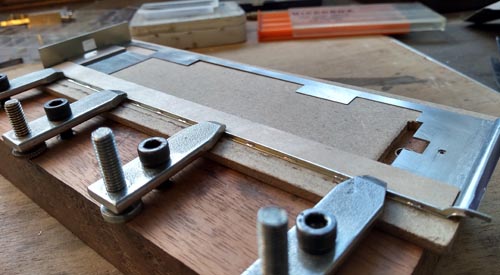
This is the setup for soldering the angles to the footplate. It needed the full length of my clamping plate. The thin strip of plywood placed along the inside of the angle provides a straight edge. Few things look worse than a wavy footplate angle. Using plywood prevents it being soldered by accident, and means I can hold it without burning my fingers.
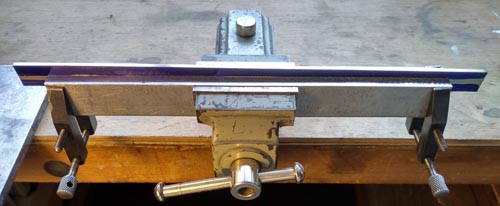
The footplate angles (or valances, if you prefer) were also cut from the same nickel silver. The photo shows my gizmo for holding long thin sheets of metal to file a straight edge to work from. It is two pieces of aluminium (mild steel would be just as good) about 6mm thick, with a dowel at each end so that they go together in exactly the same place every time. The top and bottom edges were milled dead flat and parallel. To make the clamping completely rigid I use toolmakers clamps at each end, in addition to the vice in the middle.
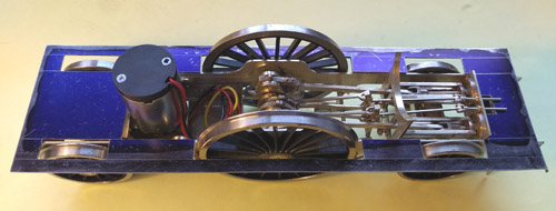
The footplate was then tried on the chassis to make sure it did clear everything it should.
Here I broke my rule about soldering on the inside. When I tried to put the plywood straight edge on the outside of the angle, so as to solder on the inside, everything got in the way of everything else and it was too difficult to keep the alignments. In the photo, I have put lots of solder tacks in place. Then I filled in the gaps between them, moving the clamps one at a time for access when necessary. Using only a small amount of solder, cleaning up afterwards was not to difficult.
The assembled footplate, with a few mounting points added to attach the boiler assembly to the footplate and attach the whole thing to the chassis. The footplate is cut away at the front (RHS in the photo) to allow access to the valve cover below the smokebox. The poor cleaners who had to get at the smokebox door must have had to balance on the front buffer beam.


