Prototype info and model design
The first problem was finding the information. After much digging and delving, we found exactly one photo and one half-decent side elevation. That was it. These locos appeared to share valve gear and inside motion with the regular Bloomers and I had a drawing of that, so that was a help. As for the rest, there would be some guesswork, but I knew I could limit that with some prior planning.
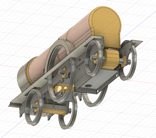
It was time to fire up the computer and do some drawing. I knew from my live steam experience, where dimensions do tend to be a bit critical, that drawing it out pays handsomely. In the past I have scrapped a few parts when I realised that something just wouldn't fit, or that it would be impossible to take apart for painting or access to the motion. So I did a solid model (aka 3D CAD) in Autodesk Fusion 360 to work out the missing dimensions and ensure that everything would fit together. It has just the basic assembly to make sure the major parts fitted and to get forewarning of any problems where they didn't. We'll come back to that later.
I wanted to use a motor and gearbox from ABC Models and it had to drive the rear axle, because the driving axle is full of cranks and eccentrics. For the said inside parts I decided to use castings from Laurie Griffin. I bought all these in advance so as to measure them and include as much as necessary (motor, gearbox, cranks and slidebars) in the solid model.
I wanted to use a motor and gearbox from ABC Models and it had to drive the rear axle, because the driving axle is full of cranks and eccentrics. For the said inside parts I decided to use castings from Laurie Griffin. I bought all these in advance so as to measure them and include as much as necessary (motor, gearbox, cranks and slidebars) in the solid model.
Nick Baines • Model Engineering


The chassis is compensated. The front axle rocks about a central pivot, and the driving and rear axles are supported on equalising beams on each side, giving the usual three-point support. I have used springing and compensation (not on the same loco!) in the past. They can both be made to work and I can't say that one is inherently superior to the other. I think compensation is generally a bit easier to fit, but finding space for the equalising beams is not always easy. In this case there was enough space on each side between the frames and the gearbox for the beams.
Pickup is from the driving and rear wheels. I always try to use as many wheels as possible to ensure continuity of supply, even though the compensation should, in theory, keep all the wheels on the rails. Pickup is from plungers mounted in the holes in the sides of the ashpan. I didn't draw the pickups but I did use the drawing to locate the holes.
At that point I was confident in the design of the chassis and I could start cutting metal.


