Nick Baines • Model Engineering
Valve gear
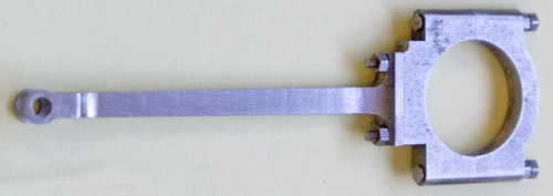
The eccentrics were made in two parts: the strap and the arm. The strap is easier, being basically two-dimensional. The only variation in thickness is in the semicircular edges where the bolts go through. It started with a blank cut to width. The rounding of the edges was done by mounting the blank in the mill at 45° using V-blocks, and making two cuts, one each side, to remove the edges, then finishing by hand with a file.
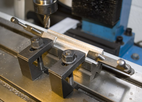

Eight pieces were sliced off, two for each strap, and machined to size. Holes for the through bolts were drilled in one set. Each pair was put together and held with a small drop of Loctite. The holes were then drilled right through and the bolts put in place to hold the two parts securely.
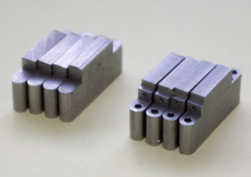
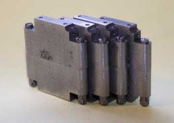
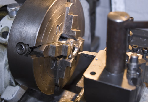
Each assembly was centred in the 4-jaw chuck and the centre was bored out to match the eccentric on the axle. The profile of the strap was finally finished in the rotary table.
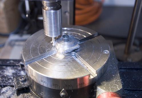
The arm is a more complicated shape. It is necessary to cut profiles in the side elevation and the plan directions. I started with the side elevation, by drilling a hole for the pivot where the eccentric rod connects to the expansion link in what will be the fork end, and the two holes forming the concave shapes at the shoulders. Then the top edge was rough sawn to reduce the amount of metal to be milled away.

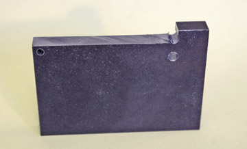
Next I started to cut the plan profile by mounting the blank vertically, cutting the slot between the forks using a slot drill, and cutting the curves in the sides by plunging an end mill of the correct diameter vertically.
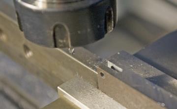
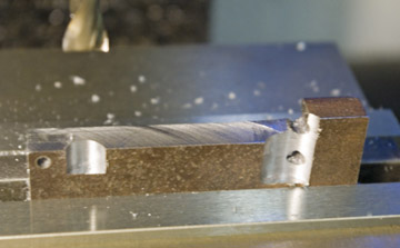
Then material was removed to bring the rod to the correct thickness, and it was cut away from the blank using a slitting saw where possible, finishing the cuts by hand with a piercing saw.
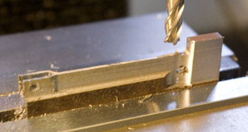
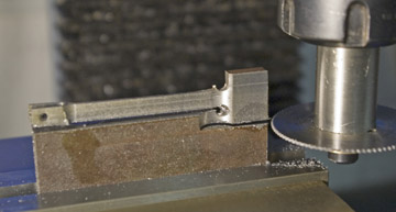
Now released from the blank, it was turned on its side. The fork ends were finished on the rotary table, and the edges of the rod were finished to size by screwing and clampling the rod to a scrap piece held in the vice, carefully aligning it before cutting each side to get the correct taper. There is a little turned spacer between the fork ends in order be able to clamp them up tight.
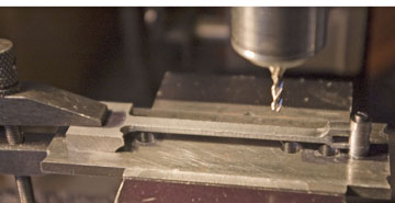
Finally the end where it joins the strap was tidied up and drilled for the studs that hold the arm and the strap together.
I've been into chapter and verse on this component. Most of the valve gear and rods were done using the same methods so I have not covered them here in the same level of detail. The important things that I've learned are, first, to think through the sequence of operations before starting to cut metal, second, to do the critical dimensions (e.g. between-centres distances and important fits) as early as possible because if they are wrong, the rest of the time is wasted, and third, make components from as few parts as possible even if it means more machining (and in this scale that is not usually a big problem).
The expansion links were also made in two parts. The link itself is a straight forward drilling and milling exercise, using the rotary table to form the various curves. The bracket was made on the end of a round bar that could be held in the vice or chuck as required, and parted off when complete. The two parts are held together with a couple of tiny screws.
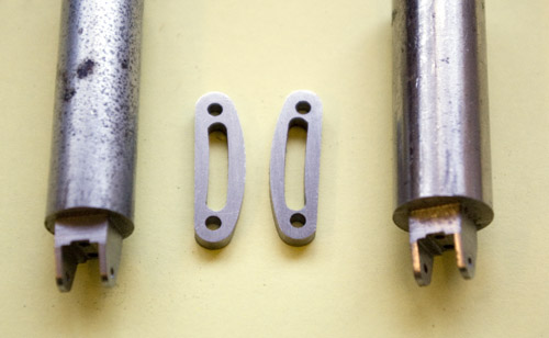
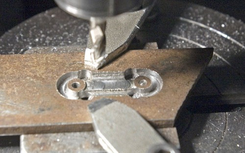
The lifting links were cut from plate, the bosses formed on the rotary table and the shank milled away. Note the shank is thinner than the bosses, so it was necessary to work on both sides of the plate. That is where a jig to hold it in exactly the same place is essential.


