Nick Baines • Model Engineering
Driving wheels and axles
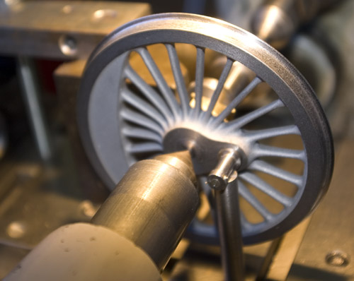
Mark Wood's wheel castings were a real pleasure to turn, and the results looked fine. I will not go into detail because I followed more or less the procedure described on Mark's web site. I had turned many castings in smaller scales, so there were no surprises.
The axles were turned from 10 mm silver steel, very nearly scale diameter, reduced to 9 mm at the wheel hubs. I aimed for a very light interference fit on the wheels, and mostly achieved it. But before the wheels could be fitted in place, there was the matter of the eccentrics on the front axle, and of getting everything set correctly.
The eccentrics are secured with grub screws so they can be adjusted if I get it wrong the first time.

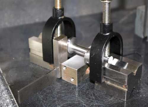
The first pair of eccentrics were set on the surface table, by pressing them against a block of carefully calibrated thickness to align them at the correct angle to each other.

The axle was rotated 90°, using a square to check the setting of the first pair (now further from the camera), and then the same block was used to set the second pair.

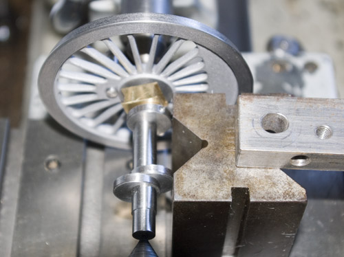
Now for the wheels. The axle was set between centres on the lathe, and the first wheel was put in place. The crank pin was pressed against a pillar of the right height to hold it exactly horizontal with the axle.

At the same time, the eccentrics were pressed up against this block to ensure that the crank pin is correctly aligned with the eccentrics. The wheels are held in place with Loctite, so all this had to happen before it went off. Needless to say, I practised a few times before doing it for real.

Then the second wheel went in place, using another pillar on the crank pin to ensure that the two crank pins are at 90° to each other. It is more important to get the crank pins correctly aligned with each other than with the eccentrics, because the eccentrics can be adjusted later, but the wheels can't.


