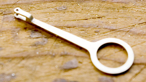
Eccentrics and straps. The eccentrics are simplified because there just isn't enough room on the driving axle between the gearbox frame and the hornblocks to represent them fully, and they will be impossible to see when the body is in place. So the strap is simply a circular hole running on the eccentric, and it cannot move sideways because there is nowhere for it to go.
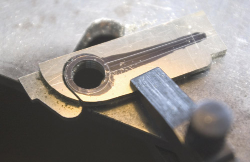
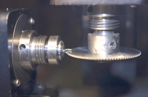
I cut four blanks of 0.7mm nickel silver, soldered them together, and here they are mounted on the faceplate so that the holes for the eccentrics can be bored accurately to size.
I cut four blanks of 0.7mm nickel silver, soldered them together, and here they are mounted on the faceplate so that the holes for the eccentrics can be bored accurately to size.
Then they were marked out and cut roughly to size with a piercing saw.
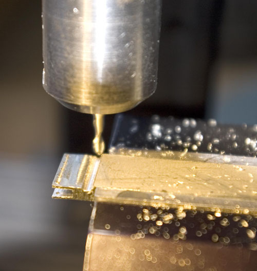
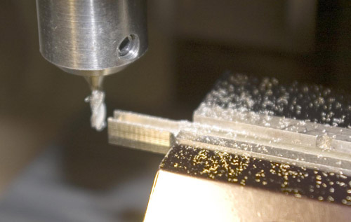
The forked ends are separate. All four were made together in the end of a bar of nickel silver using a slitting saw, and a ball-end cutter was used to shape the outer surfaces.
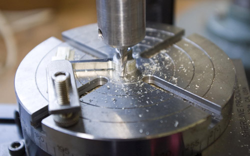
The outer radius was finished on the rotary table.
Then they were parted off, turned around, and another slit, very small this time, was made to locate the ends of the eccentric rods so that they could be soldered up.
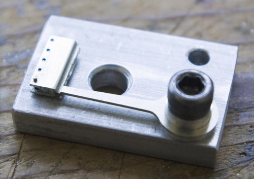
A jig holds the rod and fork end for soldering. I soldered each one in turn before parting off the fork end. Yes, there are five fork ends. The bar was wide enough so I made an extra in case one was messed up.
Finally cleaned up with files.
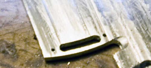
Expansion link. The expansion link slot and outer radius were cut on the rotary table. I could not do the inner radius because that is not a simple radius, it has a swelling where the link is attached to its bracket. The rest was cut out by hand and finished up with files.
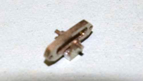
By planning the work, I was able to cut the expansion link bracket at a single setting.
The link and its bracket soldered up.
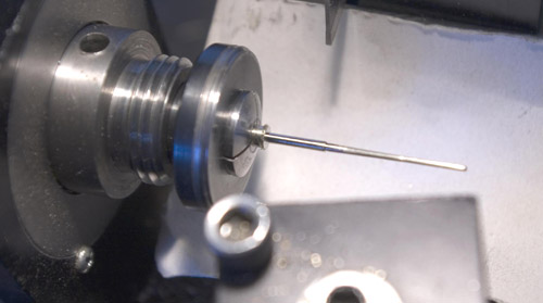
Piston rod. I turned the taper part of the piston rod in a series of steps, then finished it with a file. That is easier than setting the headstock over such a small angle.
Here the rod has been parted off and is reversed and mounted in the dividing head to cut the four square faces and the forked end.
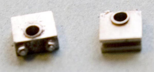
Reversng rod brackets. These brackets slot over the top of the frame and hold the reversing rod in place. They are finished off with dummy nuts from Scale Hardware
Eccentrics. The eccentrics are plain (no flanges) because there is so little room on the driving axle between the gearbox and the hornblocks that the eccentric straps stay in place.
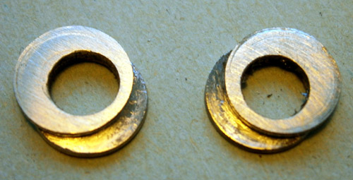
I turned a rod of phosphor bronze (more hard-wearing than brass) to size, and offset it in the 4-jaw chuck to drill the bore slightly undersize. Individual disks were then parted off, cleaned up, and soldered together in pairs. The valve gear only has to go round and look good, so exact settings weren't necessary. Then each pair was gently reamed out by hand until it was a good push fit on the axle.
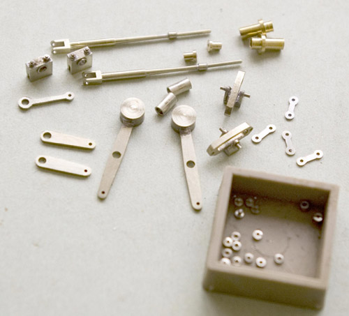
The last photo shows most of the valvegear parts before assembly.
Valve gear



Nick Baines • Model Engineering


