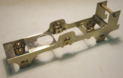
The first step was assembling the frames and spacers. The spacer with a big hole is the motor mounting plate, and was not part of the original design. When I received the motor and gearbox, I realised that Brian had designed the motor to mount vertically, not horizontally as I had assumed.
Here is the motor and gearbox. I centered it carefully on the driving axle and locked the pinion in place. The eccentrics are an interference fit and were pushed on to the axle, remembering to put the straps on first. The straps, expansion link, and piston rod were all assembled. That was the easy bit.
The hard part was getting the driving axle assembly into the chassis, with the hornblocks on the axle to slide into their guides, with the springs in place, while at the same time getting the motor through the hole in its mounting plate and the piston rods through their guides in the motion plate. And then having to work between the frames to connect the expansion links to the reversing rod. Having finally got it all assembled, I swear I will do anything rather than dismantle and reassemble it. Ever.
I could not use the plunger pickups that I prefer, because with the gearbox and the valve gear in the way there was nowhere to put them, so they are simple pieces of phosphor bronze wire. I also picked up off the trailing wheels, because I decided that picking up from the driving wheels only might not be completely reliable. I was concerned that it might be too much drag on them, but in fact there is enough weight to keep them turning.
Assembling the chassis


Nick Baines • Model Engineering


