Chassis components
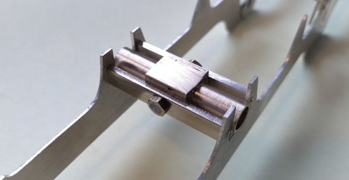
On the prototype the cylinders are attached to the smokebox and dropped between the frames. On the model, they are a separate component attached to the frames, and the smokebox will sit on top. Here is a picture of the cylinder components: front and rear plates and the U-shaped wrapper. A couple of frame spacers have also crept into the picture.
Thw wrappers are bent up from flat plate. Model making involves lots of parallel sided components. I mark them out by starting with one straight edge done by sawing, filing, and finishing by rubbing on a sheet of emery on a flat surface. The parallel edge is marked with the calipers shown in the photo. They started life as drawing compasses, and have one sharp hard point for marking, and one blunt end for guiding along the existing straight edge. Then saw, file and finish with emery the new edge.
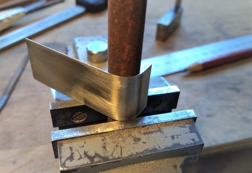
The bend radius required was too small for my rolling bars, so I did it by eye around a piece of round bar material of radius slightly smaller than the finished size. It is difficult to be specific about the radius of the former because it depends on the thickness and hardness of the sheet material, but about 80% of the finished radius seems about right in most cases.
Getting the two bends correct in relation to each other was tricky and required some trial and error. Do the first bend, then do the second bend a little bit at a time, checking against the front and rear plates to ensure it fits properly. The wrapper is cut out over length and reduced to size after assembly.
Nick Baines • Model Engineering
Assembly was by holding the front and rear plates at the correct spacing using a couple of bolts through the holes for the piston rods (which is why there are holes in the front plates also, the piston rods don't actually poke through the front plate as they did on some locos) and the wrappers were soldered in place.
Next up were the driving wheel springs.
Next up were the driving wheel springs.
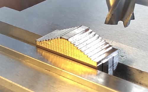
I could not find any suitable castings in brass (and I dislike whitemetal) so once again it was a case of making my own. Begin with a length of brass clamped to the mill table, and clamp a tool with a very small radius point in the mill, with the shaft locked so that it cannot rotate. Bring the tool down so that it firmly touches the work piece, and use the x-axis motion to engrave a line along the work. Increment the y-axis by the thickness of one spring leaf, and repeat.
Turn them over, remove the excess material and drill holes for the hangers. The spring shackle is a piece of thin material wrapped around the centre of the spring. The last photo here shows the spring soldered to the driving wheel keeper, which is secured to the frame using screws. The upper ends of the hangers just disappear behind the frames. You're looking here at the reverse side of the spring which I did not bother to engrave - there are limits!
At last I could stop making bits and do a trial assembly. It always seems worth doing just for that feeling that I am accomplishing something. First the equalising bars go on the frames, and then the frames are held by two spacers at the front axle on which are suspended the front axle box, and a temporary spacer at the rear.
Front axle box in place. The screw pivots allow it to rock about a longitudinal axis.
The cylinder assembly clamped and soldered in place.
The firebox assembly was soldered in place, and the rear axle with the motor/gearbox unit was added. Connect pickups, apply some volts and make sure it runs.


Cut out the blanks, one for each spring. Mount them together in the mill vice in the conventional way and cut the leaves to size.


It ran, but it was not sitting quite right. Instead of the frame being parallel to the track, it was sitting up at the front just a bit. Drat! Obviously some misalignment had crept in. Even worse, the design of the suspension of the front axle left no way to adjust the height. There was nothing for it but to replace the two parallel spacers holding the axlebox with a single spacer above the axle, and a stirrup piece screwed to the spacer that holds the axlebox in place and still allows it to pivot.

By adding spacers between the stirrup piece and the spacer it was possible to adjust the height of the front axle and get the chassis to sit just right. Another lesson learned.


