Frames, firebox and ashpan
One great thing about a solid model is that you can make 2D drawings of individual components. The frames have a complicated shape that would be tedious and error-prone to mark out. Fusion 360 allowed me to print the frame outline on self-adhesive paper that can be cut out and stuck on the metal. I use nickel silver, 0.7 mm thick which is about scale size. I tack soldered four blanks together (remember, I'm making two locos) and stuck down the frame drawing.
The hornguide dimensions are a bit critical, so I cut them on the mill to make sure they were square, parallel, and correctly spaced. I also drilled a few holes I would need. Then it was out with the piercing saw for the rest of it. Some people have trouble with a piercing saw, but keep practising, it will come. With this thickness of metal use a coarse blade, a spot of lubricant (I use candle wax), and it cuts quite quickly.
Nick Baines • Model Engineering
While I was about it, I did the equalising bars in the same way. The driving and trailing wheels are very different diameters, hence the odd shape.

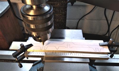
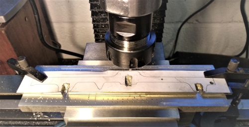
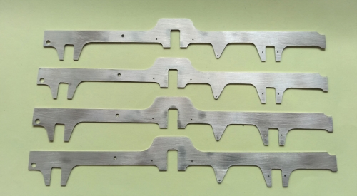
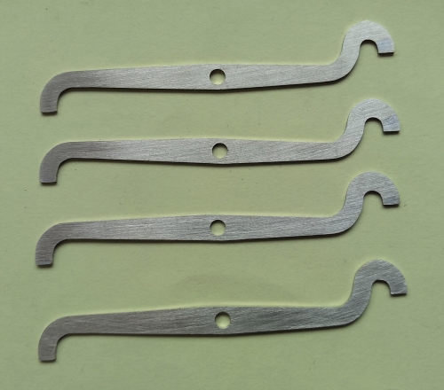
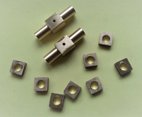
The front axle rocks about a central pivot, and runs in a canon axlebox. The bearings for the other axles are turned and grooved for the frames.
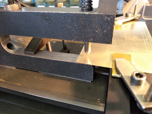
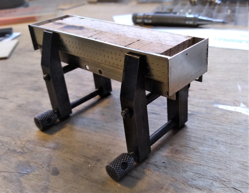
Between the driving and rear axles is the lower extension of the firebox, and beneath that the ashpan. The stays and rivets on the firebox sides are simulated using my riveting tool. This is something I made myself, but it is just like the ones you can buy from various suppliers. Here I mounted it on the lathe bed and clamped the work to the cross slide. Then I can use the lead screw and cross screw to set out the rivet impressions in a square array.

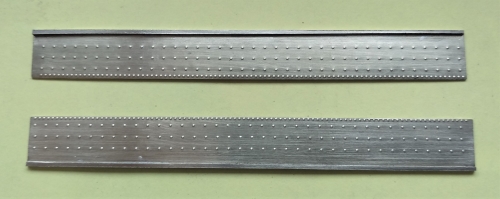
Here are the sides of the firebox done. There are actually two sides in each piece. I cut them at a later stage in the assembly.
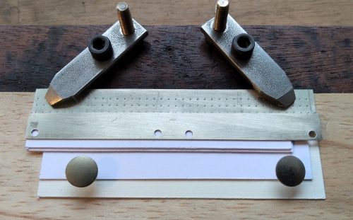
Next up are the ashpan sides, which have holes for the plunger pickups. The hole spacing was worked out from the drawing, and I made a drilling template. The template makes sure that the hole spacing is identical, but also that the holes are round. I find it very difficult to drill large holes in thin sheet, because the drill tends to snatch and distort the material. The alternative is to start with a very small drill and increment upwards to the final size, but that is very tedious if there is more that one hole to cut out.


The firebox and ashpan sides were soldered together. Lots of pieces of card used for packing. I knew I'd have a use for all those business cards after I retired.
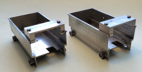
The two side assemblies were clamped together with a piece of wooden packing to give the correct spacing, and the ends are soldered into place. The ends are oversize and were cut and filed to size afterwards, to give a good appearance at the corners. Finally, the whole thing was cut half to give one for each loco. Floor added for mounting the pickup plate.
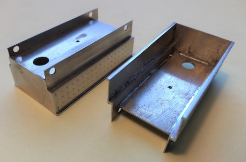
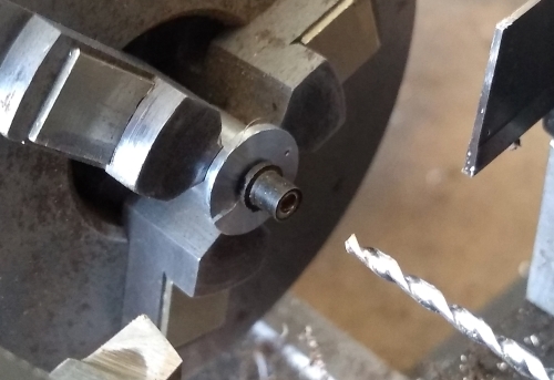
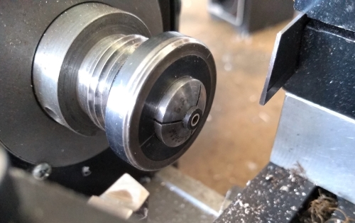
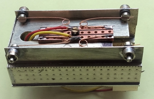
The motor-gearbox unit sits inside the firebox. I added a strap to prevent it rotating about the axle. I also soldered mountings for the plunger pickups to the sides of the ashpan. The plunger bodies were turned from Tufnol, with a centre bush of nickel silver that is drilled for the plunger. The bush is there to allow the plunger to move more smoothly than it would in Tufnol. Tufnol has more friction and is not very stable dimensionally. The plunger bodies are held in place with epoxy, and the plungers themselves are brass turnings with springs from phosphor bronze wire.
