Rods and cranks
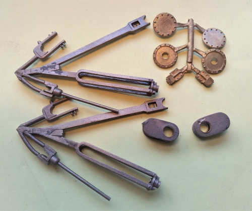
I decided to make use of some of Laurie Griffin's castings for the internals in order to save some time. The problem is that they are castings and, even though the casting quality is good, they need a fair amount of cleaning up. That applies particularly to the bearing surfaces of the cranks and eccentrics. They need a good finish to run smoothly (remember that the driving axle is not the powered one, so minimum friction is critical for free running). Setting up the castings on the lathe in order to turn the finished surfaces is not easy (read: all but impossible) and so I had to finish them by hand.
Incidentally, Laurie in his instructions recommends that when the gear is assembled, it is run in using a grinding paste. I have to part company with Laurie here, that seems terribly crude and open to all sorts of problems. I planned to fettle everything during assembly so that it works properly from the get-go.
Incidentally, Laurie in his instructions recommends that when the gear is assembled, it is run in using a grinding paste. I have to part company with Laurie here, that seems terribly crude and open to all sorts of problems. I planned to fettle everything during assembly so that it works properly from the get-go.
First up was the driving axle. I cleaned up the cranks and eccentrics as best I could. The cranks are secured to the axle which is then cut away between them. That is one joint I definitely don't want coming loose. In other locos I had assembled the cranks on the axle using Loctite and, to be doubly secure, put pins through the crank webs and axle. It works, but I thought this time I would try silver soldering just to see if it had any advantages.
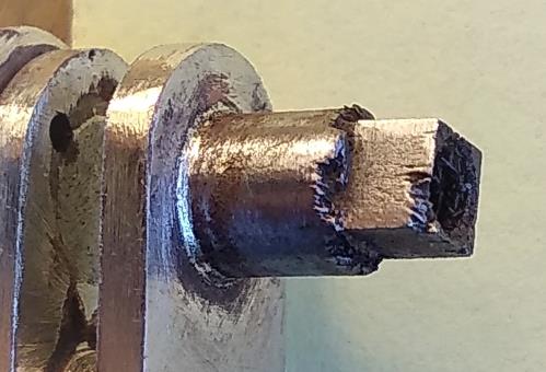
Big mistake! The heat of the flame burnt the end of the axle causing significant damage where the wheel sits.
Big mistake! The heat of the flame burnt the end of the axle causing significant damage where the wheel sits.
Nick Baines • Model Engineering
Okay, there is a lesson to be learned there. The distance from the crank to the axle end is short enough that I doubt that I could avoid damage like this entirely, even with very careful control of the flame. But my philosophy is that you only find out these things by trying them.
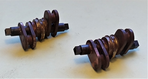
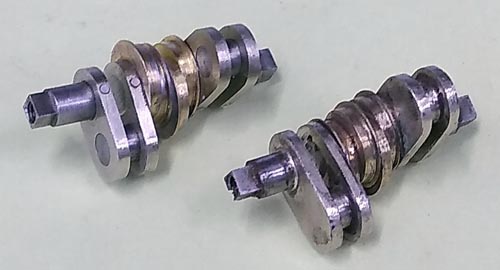
When I tried to assemble the wheels on the axles, I found that one axle was just about okay - the wheels were held securely and sufficiently near square on the axle - but the other one gave a pronounced wobble that was impossible to correct. Oh dear. Fortunately I had a spare Slater's axle and I was able to machine a new set of cranks and eccentrics. That meant that the cranks were the right size (Laurie's give a crank throw that is slightly too large, which I was prepared to overlook), but the main thing was that the finish was much better, as the photo shows. (The top one is the machined axle, the bottom one is the salvaged cast axle).
The crank axles were made a tight push fit in the webs, and the webs and eccentrics were attached to the axle with Loctite. The webs were then drilled and pins driven through to be totally secure.
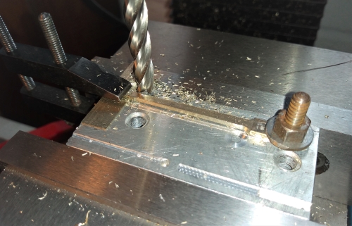
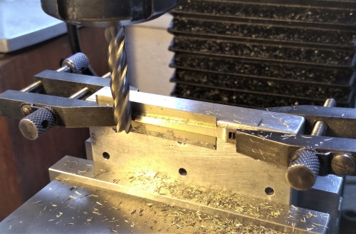
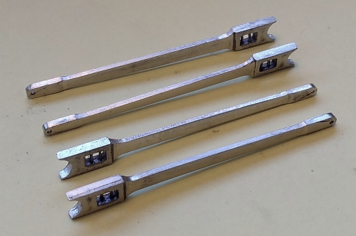
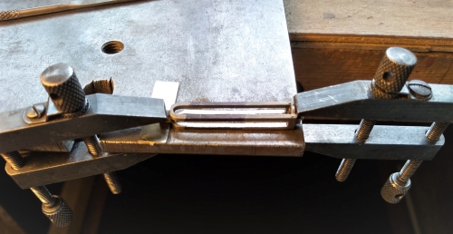
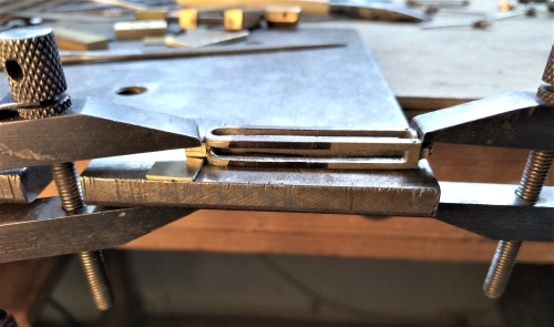
I made up a jig to hold the casting by the big end, and drilled the hole for the little end. Then in the same jig, I offset the little end first one way and then the other in order to taper the edges of the rod on the mill. The jig was then held vertically in the vice in order to reduce the sides of the rod to size. The little ends are purely functional, I did not put any detail because they are hidden in the crossheads.
The loco has a 4-slidebar assembly, with the front ends of the bars attached to the rear cylinder cover and the rear ends to the motion plate. The casting comprises the bars and part of the rear cylinder. The bars have to be cut to length in order to fix them to the motion plate. Due to the casting process, the surfaces were a bit rough and the bars were not entirely straight or parallel. The casting material is also very soft, which means that the bars are easily bent.
Before doing anything else, I cleaned up the inside and outside surfaces of the bars by filing and carefully straighened where necessary.
Before doing anything else, I cleaned up the inside and outside surfaces of the bars by filing and carefully straighened where necessary.
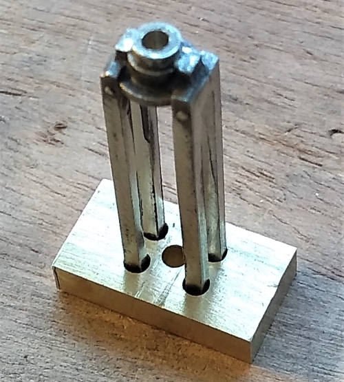
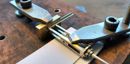
Then I cut the casting away to release the rear ends of the bars. To make sure that the bars stayed in the right positions and at the right spacing, I made a little jig to hold them, which has four holes at the correctl spacing. The holes are just large enough to slide over the bars. I could then use the jig to hold the bars in order to solder little bits of angle at the point where they would meet the motion plate. Once that was done, the bars were cut to their finished length.
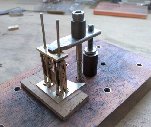
The photo shows the crosshead and piston rod are already in place. The design of the motion plate on the prototype is such that the crosshead must go in place before rather than after assembly. The crosshead was easy to clean up but the piston rod was not. Another time, I would retain the cast crosshead and replace the rod with stock rod nickel silver.
The photo shows the crosshead and piston rod are already in place. The design of the motion plate on the prototype is such that the crosshead must go in place before rather than after assembly. The crosshead was easy to clean up but the piston rod was not. Another time, I would retain the cast crosshead and replace the rod with stock rod nickel silver.
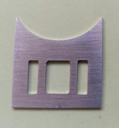
Here are the motion plates, cut from nickel silver plate. The slidebar assemblies were held in place and soldered to the plate. Another jig was used to locate the front (uppermost) ends of the slidebar assemblies at the correct spacing.
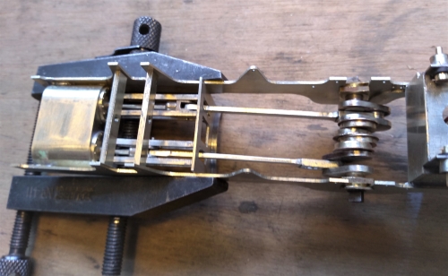
And finally, a trial assembly to make sure everything works as it should.
After that bit of excitement, the connecting rods were more mundane. The casting is designed for many different prototypes, and has a detailed big end, but you have to make your own little end and shape the rod itself.
