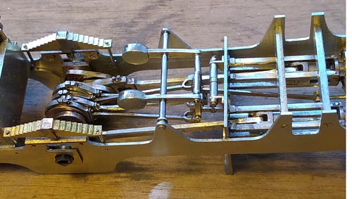
Valve gear
The eccentric rods were made from Laurie Griffin's castings. Laurie splits the eccentrics in half following the prototype, and the rod itself comes in two parts to allow different lengths for different locos.
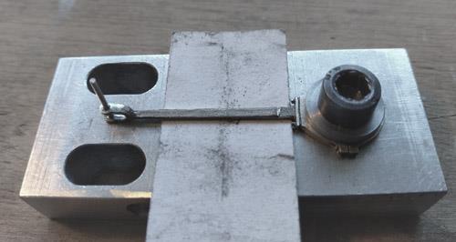
To assemble the rod, I turned a clamping piece to hold the eccentric end to a scrap piece of aluminium, and drilled a hole for the fork end at the correct spacing.
Nick Baines • Model Engineering
The expansion link was unusual in that it had a central slot for the radius rod which moved inside the link. The curved slots allowing the rod to move between forward and reverse gears were inside the link. Laurie did not have a suitable casting, but since most of it was hidden inside, it was easy to make, particularly because I fixed the radius rod in one place (mid gear) rather than allow it to move. It is a nice gimmick to make the gear so that it can be reversed, but of course on an electrically driven model it is just that - a gimmick.
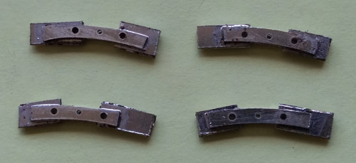
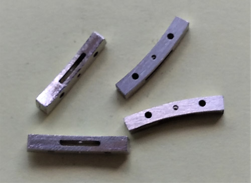
The expansion link was made as two sides, drilled and cut out on the rotary table, and soldered up with spacers, one at each end, to give the central slot where the radius rod goes. The spacers were oversize and were cut and filed back after soldering.
The expansion link was made as two sides, drilled and cut out on the rotary table, and soldered up with spacers, one at each end, to give the central slot where the radius rod goes. The spacers were oversize and were cut and filed back after soldering.
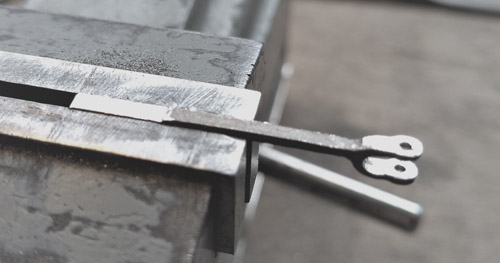
The rounded ends of the forks were made by filing, using a "toolmakers button", which in this case was a little piece of silver steel turned to the correct diameter and made a nice fit in the fork. It was then hardened to prevent wear. Then it was back in the lathe to have the shank turned down, and finally parted off.
Finally the fork ends were thickened up with turned washers, and the spindles were soldered in place.
The divided bearing was made and assembled as a single part, and then slotted for clearance for the valve rod. Unfortunately I forgot to photograph it at that stage.
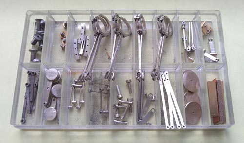
Here's all the valve components (and a few others) ready for assembly.
Here's all the valve components (and a few others) ready for assembly.
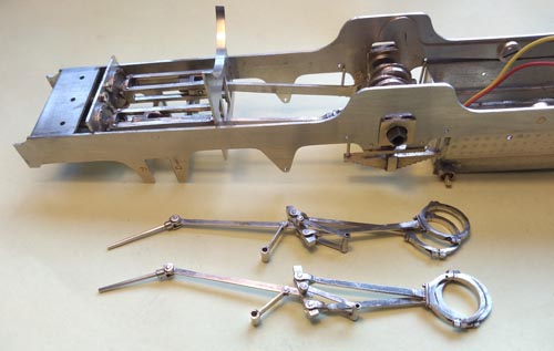
As much as possible was assembled on the bench before going into place.
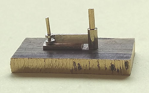
I've been accused (if that is the word) of using a lot of jigs. I do it, first, to ensure dimensional consistency. If I make four parts, I want them to be the same size and thus interchangeable, rather than having everything made to fit. And second, because it is so much easier to solder if they can't go wandering about the bench. I think you can see that most of the jigs are very simple, often just a scrap of material with a few holes drilled in the right places.
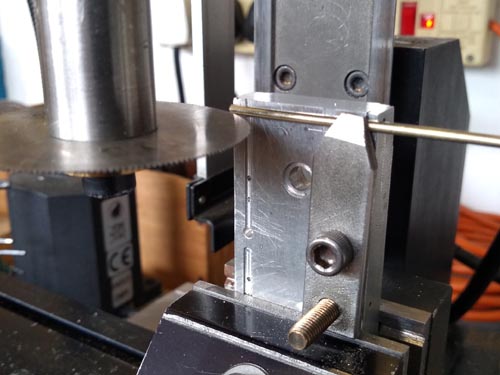
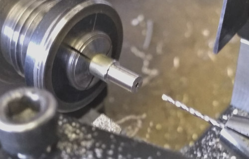
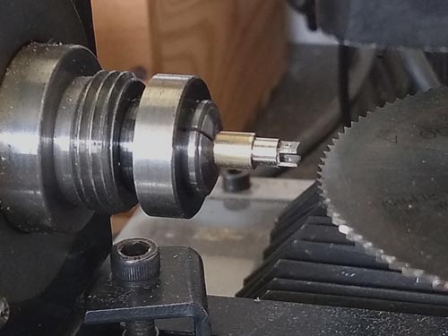
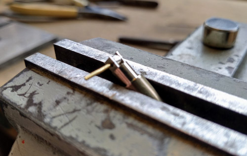
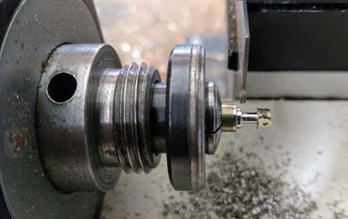
The valve spindle has a fork end for where it joins the radius rod. The fork end started as round bar, drilled centrally in the lathe for the spindle. Then, still held in the collet, it went to the dividing head on the mill, flats were cut on the outside surfaces and the slot was cut using a slitting saw. Using the same setting, the fork was drilled for the pivot.
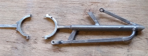
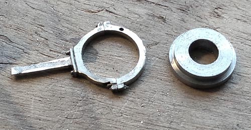
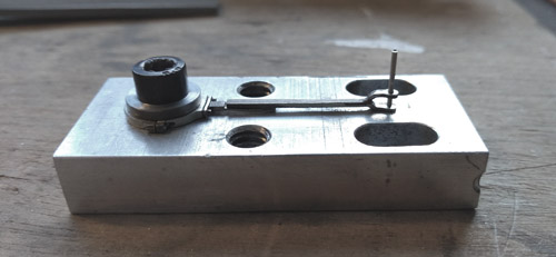
Both pieces of the rod were filed to half thickness where they overlapped, and were then soldered together. With a good overlap, the joint was quite strong enough. The rod was then cleaned up with files and emery.
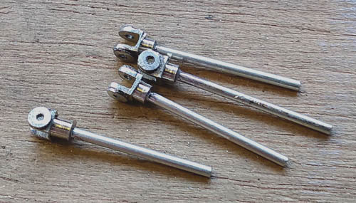
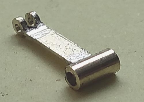
The links that support the expansion links are a rather unusual design.
The bearing surfaces at each end were made from rod of the right diameter, drilled out and a slot for the link was cut using a slitting saw, going just deep enough to support the link. The bearings were held at the correct spacing in a jig and everything was soldered up.
