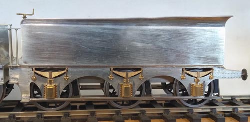
Tender
The loco is driven on the trailing axle and I cannot get enough weight on that axle to prevent the wheels slipping at the slightest provocation. So the tender has to be weighted and the weight transferred to the engine via the drawbar. The rear axle of the tender runs in fixed bearings, and the front and centre axles are allowed vertical movement and are lightly sprung, just enough to keep the wheels on the rail without taking weight that would otherwise be transferred to the engine.
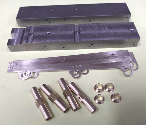
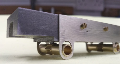
The chassis is a big chunk of steel (for weight) with the inner frames attached to it. The prototype tender had a well tank between the frames, which is simulated by the steel spacer. The front and centre axles run in canon axleboxes with a centre spring - a nice simple solution.
The chassis is a big chunk of steel (for weight) with the inner frames attached to it. The prototype tender had a well tank between the frames, which is simulated by the steel spacer. The front and centre axles run in canon axleboxes with a centre spring - a nice simple solution.
Nick Baines • Model Engineering
The outer frames had a complicated pattern of rivets, and to reproduce that I made a jig with holes where the rivets go. Each frame in turn was clamped to the jig, and the rivets were pressed using a tool that was turned down to pass through the holes.
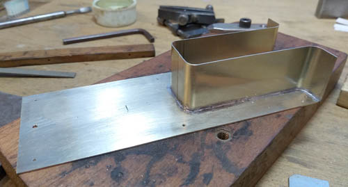
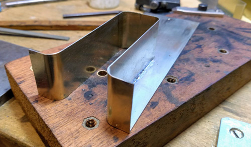
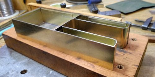
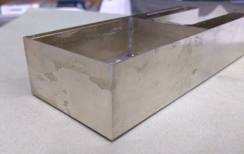
Now for the tank. Curse the LNWR for having a coal space that went right down to the footplate because making all those bends in the right places is tricky. The bends themselves were done between two rods of the appropriate diameter that could be clamped together using screws. I made the inset piece in two halves, joining at the centre of the back wall of the coal space where it would be concealled by the coal load.
The method was to make the sheet over length, do one bend, check it against the base of the tank, and use that to get the other bend in the correct position. Tricky, but with care it works. Then cut to the correct length and solder in place.
The method was to make the sheet over length, do one bend, check it against the base of the tank, and use that to get the other bend in the correct position. Tricky, but with care it works. Then cut to the correct length and solder in place.
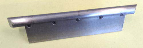
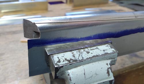
The flares on the top edges of the tank were the last major components. They were curved, but thankfully the corners were mitred (unlike some companies that went in for curved flares and curved corners to the tank) so they were not as bad as they might have been. Here is the tool I made to form them. The flare is bent over a circular rod of diameter somewhat smaller than the finished flare to allow for spring in the material. The rod was rebated and attached to a flat piece of material so that the blank from which the flare is formed could be clamped to it. The ends of the rod were cut at 45° to make a former for the mitred ends.
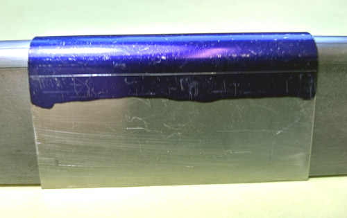
This is the flare on the end of the tank. It was curved over the forming tool by hand, with the aid of another rod. The scribed line is where it will be cut to separate the flare from the rest of the material.
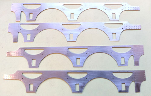
The outer frames were cut using a printed paper pattern of the outline, just as for the loco frames.
Then the outer sides and end went on. The sides were made slightly over long and cut back when everything was soldered up. That way it is possible to get a nice sharp corner that looks as it should.
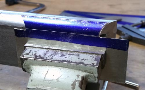
Now waste material at each end was cut away and each corner was formed by filing up to the 45° end of the tool.

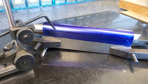
The sides were done in the same way, but with the added complication that they are tapered. The taper line here is being marked out. Notice that the tool is raised at one end using a rod of suitable diameter to get the correct taper.
The flares were finished with a nickel silver wire along the top edges to represent the reinforcement there. Here the wire is being tacked into place before finally soldering up along its length.

And the forming tool was used once more to file off the end of the wire at 45° at the corners.
The flares were then cut off and attached to the sides and end. This photo shows the final assembly of the tender. The springs and axleboxes were made by Shapeways, 3D printing in brass from my solid model. Not cheap, but the results are superb. The finish was good enough that no hand finishing was required, and they were dimensionally accurate and went into place exactly.
