Nearly finished. Just a few boiler fittings, the weatherboard and the cab floor to add. The chimney really is vertical - what you can see is camera lens distortion.
And so, after nearly ten years, it was finally done. Although to be fair, it only took that long because other projects got pushed in front of it. Usually I reckon to be a bit faster than that. People often ask how long a project takes. So the answer is ... between one and ten years ... depending ...
I'm pleased to have done something that is almost the ultimate in scratch building. The motor and gearbox are the only purchased components, everything else comes from the raw metal.
Once again, Ian Rathbone came up trumps with the painting and lining. With prototypes as old as this, the colour scheme is usually a bit of a guess, but we agree that his choices were very plausible.
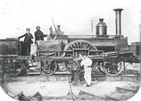
LSWR Mazeppa Class
This is the LSWR Mazeppa class 2-2-2 of 1847, designed by John Viret Gooch (older brother of the more famous Daniel). Once again, details are in Bradley's book, including a reproduction of drawings published in Railway Machinery by D. Kinnear Clark in 1855. While they are not works drawings, they do show all the internal details, so it is probably safe to assume that Kinnear Clark had the cooperation of the Nine Elms drawing office.
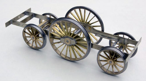
Like many other prototypes from this time, the construction was not straight forward. There was no obvious way to divide the body and chassis, so the frames form a central "backbone" to which everything is attached in one way or another.
All the wheels were machined with solid centres in brass, a turned rim soldered in place, and then a steel tyre. Unfortunately scratch building was the only way to represent properly the thin, rectangular section spokes and the balanced boss on the driving wheels.
I used a form of compensation. The front axle pivots about the centre of the frames, and the driving and rear axles are supported on beams. The pivot point of the beam is biased towards the driving axle (the screw head is visible in the photograph) so that more of the weight is transferred to the driving axle than to the trailing axle - a simple principle of mechanics that was pointed out to me by Brian Clapperton. The centre of gravity of the loco has to be between the leading axle and the beam pivot point, if it is behind the beam pivot, the loco just tips onto the rear axle and unloads the front axle completely. Thus, weight distribution is important.
The smokebox was tricky, because the assembly incorporates the cylinders which are set at an angle to the smokebox itself. Both the front and back plates are awkward, and different, shapes. They are held in place by two spacers that were carefully cut to shape. In fact the whole assembly involved lots of careful measurement of the drawings, marking and cutting out, and a few crossed fingers. The effort paid off, because it all went together as intended.
The smokebox wrapper wasn't as bad as I feared. I cut out an oversize blank, formed the curve across the top using my rolling bars, then eased the rest of it into shape around the front and back plates, using an assortment of round bars to form the curves. It was then soldered in place, and then cut back with the piercing saw to leave a millimetre or less to file away to make it flush. The back edge was easy because there is no detail there to mess up, but the front plate has a row of rivets around the edge that had to be avoided. I tidied it up with a sanding disk in my Dremel, used very carefully.
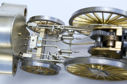
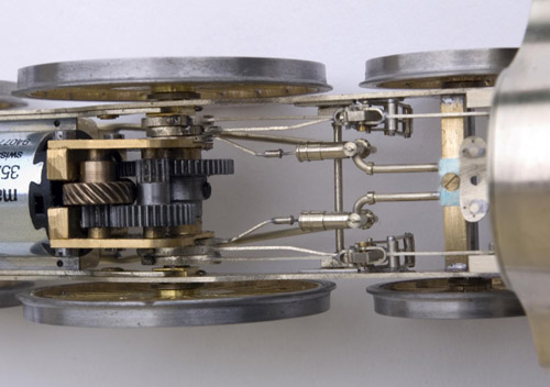
The next task was the valve gear and feed pumps between the frames. The valve gear, for those interested, is Gooch's own (this class was the first to use it). It is similar to Stephenson's, but instead of lifting the expansion link, a radius rod connecting the expansion link to the valve spindle is lifted to reverse the gear. From my perspective the main problem was getting three eccentrics on each side of the driving axle between the bearing and the gearbox. That is two to drive the valve gear and one for the feed pump. I had to thin out the frames of the gearbox (an ABC Gears product) to get them all in. There are a couple of 14BA bolts in the valve gear to allow it to be dismantled and the driving axle with gearbox removed.
This loco does not have a circular boiler. In section, it is a circle with two segments cut out at the bottom to clear the valve gear. It probably caused as much difficulty for the prototype as for the model. I decided to make it from solid because I could not see a good way to roll the reverse curves involved. Here is the boiler mounted on the vertical slide on the Myford lathe. The segments were cut out using the largest diameter boring bar that would fit.
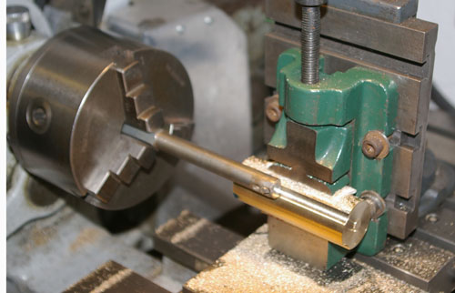
The boiler fittings are turnings, made more straight forward than usual because they all sit on square pedestals, which were separately fly cut to fit. If only later engineers had continued that system. You can still see quite a lot of the valve gear and the feedwater pumps with the boiler in place, so all that work wasn't wasted.
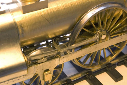
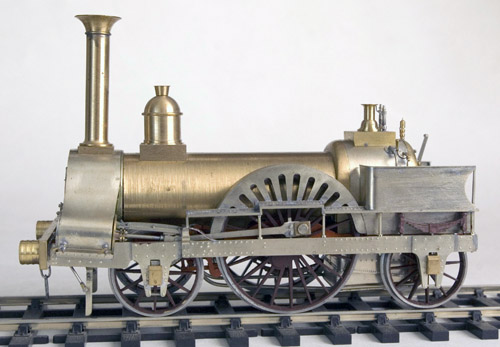
The two levers on the right of the firebox are the regulator and reverser. On the prototype, the regulator itself was located underneath the smokebox just before the cylinder valves, rather than in the boiler as was common later. The reverser most likely should have some sort of locking device to hold the gear in position, but the drawing and photographs show no evidence of that. The two taps on the right hand side of the backhead are a primitive water gauge. There is no boiler pressure gauge, the crew just relied on the safety valve blowing off.

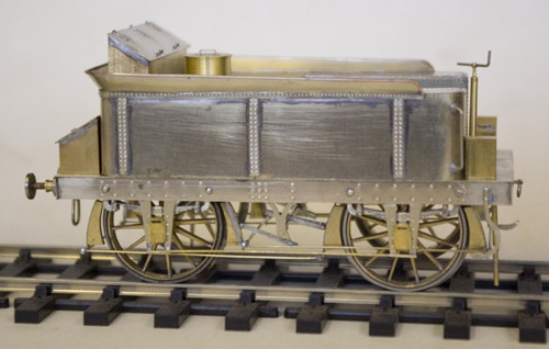
Next up was the tender. No official drawings exist, so it was done mostly from photographs which only show the side view. The ends are quite speculative. Everything is scratch built, of course, including the wheels, axleboxes and springs. The springs don't "spring", but the axleboxes are free to move up and down a fraction, and that seems to be enough. True to prototype, the axles are extended and run in the axleboxes. I wonder why we so often put up with inside frames and bearings that the prototype tenders didn't have?
The brake gear is a bit different. The inner brake blocks are actuated from the brake lever just like a conventional wagon brake gear, and the outer blocks are linked to the corresponding inner blocks on the adjacent wheel, so that they get pulled on and off together. The pull rods are outside the wheels and very visible.
The brake gear is a bit different. The inner brake blocks are actuated from the brake lever just like a conventional wagon brake gear, and the outer blocks are linked to the corresponding inner blocks on the adjacent wheel, so that they get pulled on and off together. The pull rods are outside the wheels and very visible.
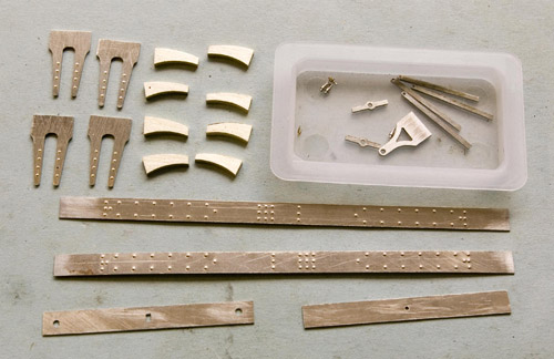
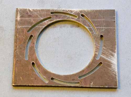
The photo here shows how I cut the brake blocks. A piece of brass plate of the right thickness was chucked in the 4-jaw and the centre turned out. It was then put on the rotary table in the mill, and the centre offset (that took some working out!) in order to cut the outer arcs. Finally, the individual blocks were sawn out. I just got the eight blocks I needed from one plate.
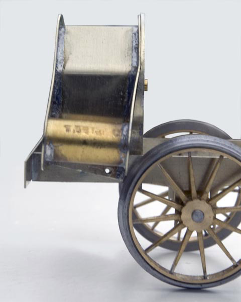
And here is the finished tender. Quite simple really (he said), not much more than a water tank on wheels. I like the lovely curved steps. They weren't as difficult to make as they may appear, just an S-shaped back with the treads curved and soldered in place.

Nick Baines • Model Engineering

