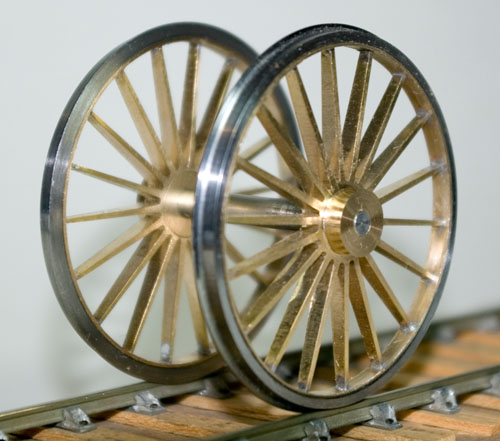
Here I describe and illustrate my method of making wheels. Be warned about what follows. This is one case where you do need a well-equipped workshop, and in particular, a lathe, milling machine, and a dividing head. I make no apologies, sometimes there is just no easy way to good results.
Making wheels
The wheel centre, comprising the boss and a disk that will soon be cut to form the spokes, is turned in the lathe to the correct profile, giving the spokes the necessary taper from hub to rim. I use brass of this. I would use nickel silver, if I had access to (and could afford!) a bar of sufficient diameter. To complete the turning, the centre is drilled and tapped (M4 in my case, though the equivalent BA size would be just as good), and mounted on a piece of 3/16 in. silver steel that has been threaded at one end. This silver steel will eventually form the axle, and is held in the lathe using a collet.
The photo shows tyres, rims, and turned centres of wheels. For this prototype, the wheel requires an extended boss. In the foreground is the disk of styrene sheet used to check the cutter setup.
The centre is now mounted in a dividing head, which allows it to be rotated in accurate increments in order to cut each spoke. The dividing head is mounted on the bed of the mill, and the cutting is done using a fine slitting saw. Because the spokes are tapered, the height of the saw needs to be carefully adjusted, initially above to the centre line of the dividing head. Once this is done, one side of each spoke in turn is cut, then the saw is repositioned the same depth below the centre line of the dividing head, and the other sides are cut. In the photo above is a disk of styrene sheet that I used first to check the saw settings, rather than risk getting it wrong on the actual part. Download an information sheet here showing how to calculate the settings for cutting.
Once the last material between the spokes has been removed using a piercing saw, the result is a centre with a lot of rather delicate spokes, and so the next operation is to solder this inside a turned rim. The rim is also made of brass, slightly oversize, and after soldering, the assembly is returned to the lathe, set dead on centre, and the rim is turned to size using very light cuts. If the driving wheel is to be insulated, this is done at the rim, and to allow for it, the rim is turned about 0.25 mm undersize. The rim of the uninsulated wheel is finished to be a nice sliding fit in the tyre.
The tyres are separate turnings in steel. For an uninsulated wheel, the centre is bored to be a sliding fit on the rim. For an insulated wheel, the steel blank is first bored out to the correct inside diameter and depth of the tyre. It is then removed from the chuck (noting the no. 1 jaw position so that it can be replaced truly), and the centre is filled with epoxy. I use slow setting epoxy, and cure it for an hour or so at 70°C in the domestic oven, which seems to give it more strength than being left to cure at room temperature. When solid and cool, the tyre goes back in the lathe and all but a thin layer of epoxy is removed, so that it is a sliding fit on the rim. In both cases, the outer profile of the tyre is then finished. I have a profile tool from AGH (alas, no longer available) which I use for the last skimming cuts to give an exact and consistent profile, but before acquiring such a useful thing, I turned tyres using standard lathe tools. It just takes longer and needs careful measurement. The finished tyre is then parted off. Finally, the tyres and centres are glued together using Loctite.
The tyres are separate turnings in steel. For an uninsulated wheel, the centre is bored to be a sliding fit on the rim. For an insulated wheel, the steel blank is first bored out to the correct inside diameter and depth of the tyre. It is then removed from the chuck (noting the no. 1 jaw position so that it can be replaced truly), and the centre is filled with epoxy. I use slow setting epoxy, and cure it for an hour or so at 70°C in the domestic oven, which seems to give it more strength than being left to cure at room temperature. When solid and cool, the tyre goes back in the lathe and all but a thin layer of epoxy is removed, so that it is a sliding fit on the rim. In both cases, the outer profile of the tyre is then finished. I have a profile tool from AGH (alas, no longer available) which I use for the last skimming cuts to give an exact and consistent profile, but before acquiring such a useful thing, I turned tyres using standard lathe tools. It just takes longer and needs careful measurement. The finished tyre is then parted off. Finally, the tyres and centres are glued together using Loctite.
Making wheel centres in multiple
This is a development of the same technique for "mass producing" wheel centres. In this case, they were carrying and tender wheels (fortunately the same design) for Mazeppa. The method means having to do the set up in the dividing head for cutting the spokes only once.
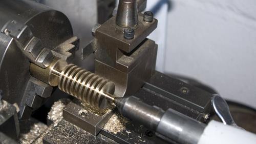
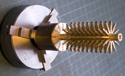
First, chuck a bar in the lathe and turn the OD of the spokes. Then with a parting tool, gash at intervals to the depth of the hub, leaving disks of the correct thickness for the spokes. Note that I'm using the tailstock to support the bar. The parting tool should be wide enough so that the gap between the disks allows for the hub dimension, plus some cutting allowance when the disks are finally parted.
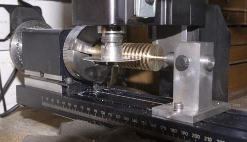
Transfer to the dividing head on the mill and set up for cutting the spokes as for a single wheel. I had to make a simple tailstock to support the bar for this purpose.
Then make a series of passes with the slitting saw through all the disks, as described above.
All spokes cut. The bar is returned to the lathe, and the individual wheel centres are parted off, using a smaller parting tool than before to leave material for the hub. Each wheel centre was then soldered to a rim, set in the lathe, and the hole for the axle was drilled and tapped.
Wheel making

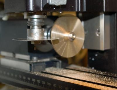
Second cut:



Nick Baines • Model Engineering
First cut: